Gill Instruments Ltd
_____________________________________________________________________________________________________________
________________________________________________________________________________________________
WindObserver 65 Page 9 Issue 4
Doc. No. 1390-PS-0039 June 2016
5.4. Connector and Cable Assembly.
The WindObserver 65 variant with a connector base is supplied with a mating 19 way
connector.
Open the pack of connector parts supplied (Gill Part 1390-10-163).
A set of assembly instructions are supplied with the connector together with:-.
Table of Equivalent Part Numbers
Part Name Gill Part No. Cannon Trident Part No.
Connector head, 19 way 020-04464 192993-0054
Metal backshell (7 pieces) 020-04465 192993-0084
Solder bucket contacts
(5 per pack, (4 –off packs))
020-04469 192900-0635
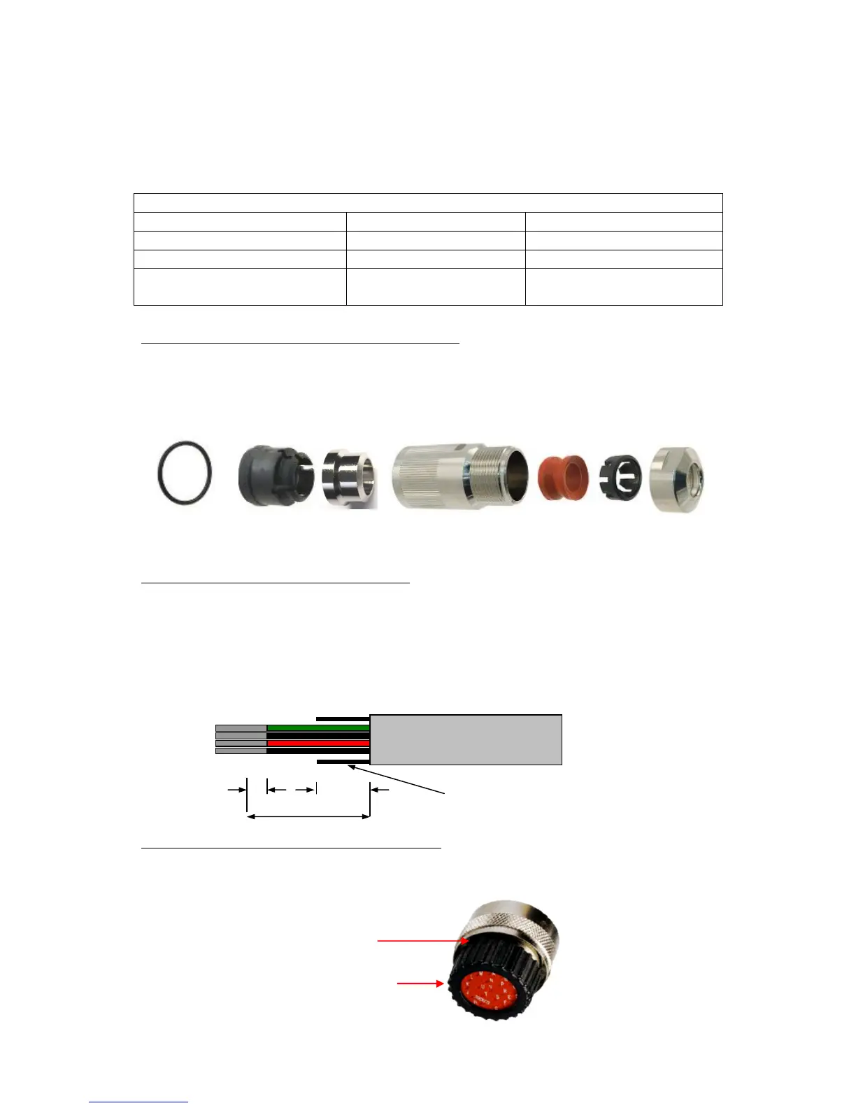
Arrange Backshell (Gill Part Number 020-04465).
Pass parts 1-6 along the cable as per the diagram below.
(Note that the connector supplies the correct strain relief for cables with an outside
diameter of 7.9 to 12.6mm).
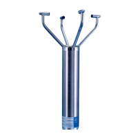
Prepare Cable (e.g. Gill Part 026-026643).
Trim back the cable outer and twisted pair screen sleeves 40mm (see diagram below).
Trim back the screen drain wires to a length of 24mm.
Strip back the connection wires by 7.1mm and tin solder.
Solder the wires to the bucket contacts (will take 14awg to 26awg wire).
Unused wires should be cut back and insulated.
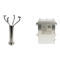
Prepare Connector Head (Gill Part 020-04464).
Remove the connector thread protector and place the O-ring (part 7) into the groove of the
connector head (020-04464).