Gill Instruments Ltd
_____________________________________________________________________________________________________________
________________________________________________________________________________________________
WindObserver 65 Page 13 Issue 4
Doc. No. 1390-PS-0039 June 2016
6.4. Power supplies
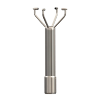
All WindObserver 65 units
Sensor Supply: -
Voltage 9 to 30v DC
Current 30mA Average. 50mA Max @12v dc (non-analogue unit)
Current 50mA Average, 65mA Max @ 12v dc (analogue unit 0-5v
setting).
The WindObserver 65 has reverse polarity protection.
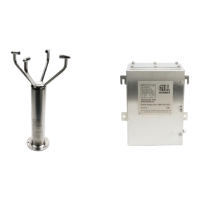
Wind Observer II Units with Heating
Heater Supply: -
Voltage 22V to 30V (max) AC RMS or DC.
Current allow for 3A.
The AC Supply must be isolated from Mains Supply.
The heating module requires a separate power supply.
Heater Cable length should be minimised to avoid cable volt drops and ensure
maximum voltage received at the Anemometer.
The heating (H command) is enabled as a default condition. If heating is not
required enabled then the H command must be set for H1.
Each transducer is heated independently and will be active when ambient
temperature drops below approximately +15ºC each transducer will de-activate
when +25ºC threshold is reached.
The WindObserver 65 has reverse polarity protection.
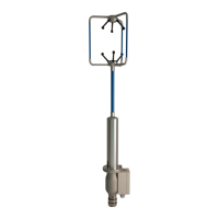
6.5. Connections
Important Any cable wires not used should be isolated and grounded at the
terminating equipment/user end.
Do NOT connect the unit’s 0V, heating –ve, analogue output 0V or digital 0V to the
screen or earth.
On units with integral cable the screens of each pair are joined together inside the
anemometer - these should be joined to the cable screen(s) of any further cable run.
Avoid long grounding loops. Digital OV should be used in conjunction with RS422 TX
RX lines in order to improve noise immunity.
Earthing or grounding
To ensure correct operation, and for maximum protection against lightning, the
anemometer MUST be correctly earthed (grounded) via its mountings. Inadequate
Earthing will degrade anemometer performance, particularly in the presence of radio
frequency interference.
See Fig 1 Suggested mounting bracket and Earthing (grounding) arrangements
The unit MUST be connected to an appropriate grounding point with a minimum of 6mm²
copper wire, via the M5 base screws. The cable screens must be joined with any cable
screen continuing from the unit’s cable via a junction box. The primary earth for the
anemometer must be provided via the base screws and not via the cable screens.