EasyManuals Logo
Home>Gill Instruments>Measuring Instruments>Windobserver 65

Gill Instruments Windobserver 65 User Manual

Gill Instruments Windobserver 65
65 pages
To Next Page IconTo Next Page
To Previous Page IconTo Previous Page
Page #16 background imageLoading...
Page #16 background image
Gill Instruments Ltd
_____________________________________________________________________________________________________________
________________________________________________________________________________________________
WindObserver 65 Page 16 Issue 4
Doc. No. 1390-PS-0039 June 2016
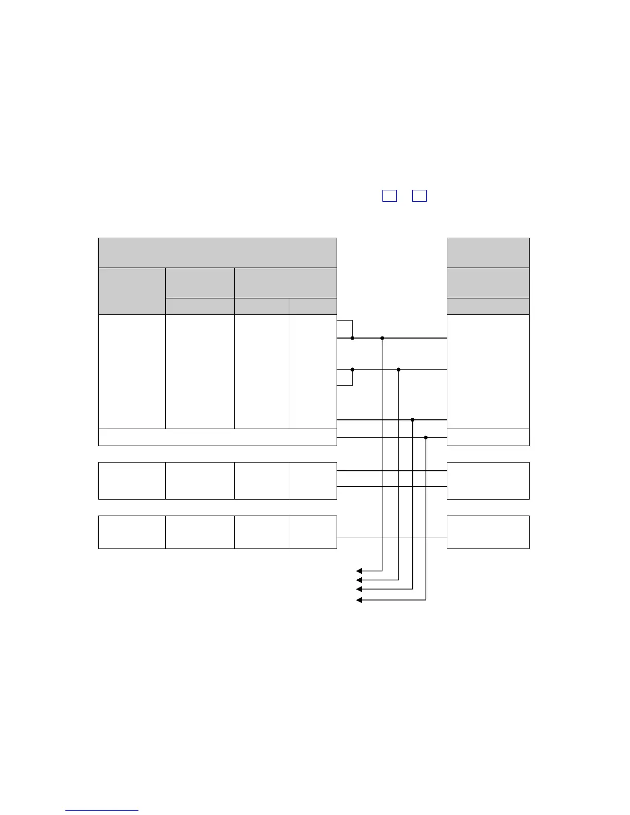
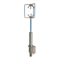
Networking units
Before coupling units into a network:
Each device must be configured with a unique Unit Identifier (letter A to Z)
however in multi drop systems it could be advised to avoid using letters A-F,
KMN and P as they could appear in the data string.
Unit must be set for half duplex mode (E2 setting) see Para 7.3).
It must be configured to a tri-state polled mode M3 or M4.
See also Section 8 - Configuring
WindObserver
6
5
Converter,
PC, or Logger
Signal
Names
19 Way
Connector
Cable Gland
RS485 2 wire
Pin No.
Pair No
Colour
Signal Names
TXB (+)
P
1
Green
RXB (+)
U
2
White
T/
RXB (+)
TXA (
-
)
C
1
Black
T/RXA (
-
)
RXA (
-
)
V
2
Black
Digital 0v
M
4
Blue
Signal Ground
Connected Internally
Ground Earth
Sensor +
R
3
Red
+ve
Sensor
Sensor
-
D
3
Black
-
ve PSU
*
Heater +
A
5
Yellow
+
Heater
Heater
-
B
5
B
lack
-
PSU *
*For Power Supply Information see Section 6.4.
Note: Each unit in the network will require its own power supplies.
To Next Unit

Table of Contents

Questions and Answers:

Question and Answer IconNeed help?

Do you have a question about the Gill Instruments Windobserver 65 and is the answer not in the manual?

Gill Instruments Windobserver 65 Specifications

General IconGeneral
BrandGill Instruments
ModelWindobserver 65
CategoryMeasuring Instruments
LanguageEnglish

Related product manuals