34
9. CONNECTIONS
9.1 CONNECTION SCHEME IP54
9.1.1 LOAD CELL
The device is completely supplied for the connection of the transducer (load cell). The kit includes:
• 1 male connector to be welded (9 tracks)
• 1 coverage/blocking cable protected
The cable that comes from the transducer or transducers is connected by welding it to the device. The user must be very careful with
its quality and the isolation between the conductors and the use of a good alloy of tin. A bad quality product or a product that is not
appropriated could damage or alter the correct working of the device..
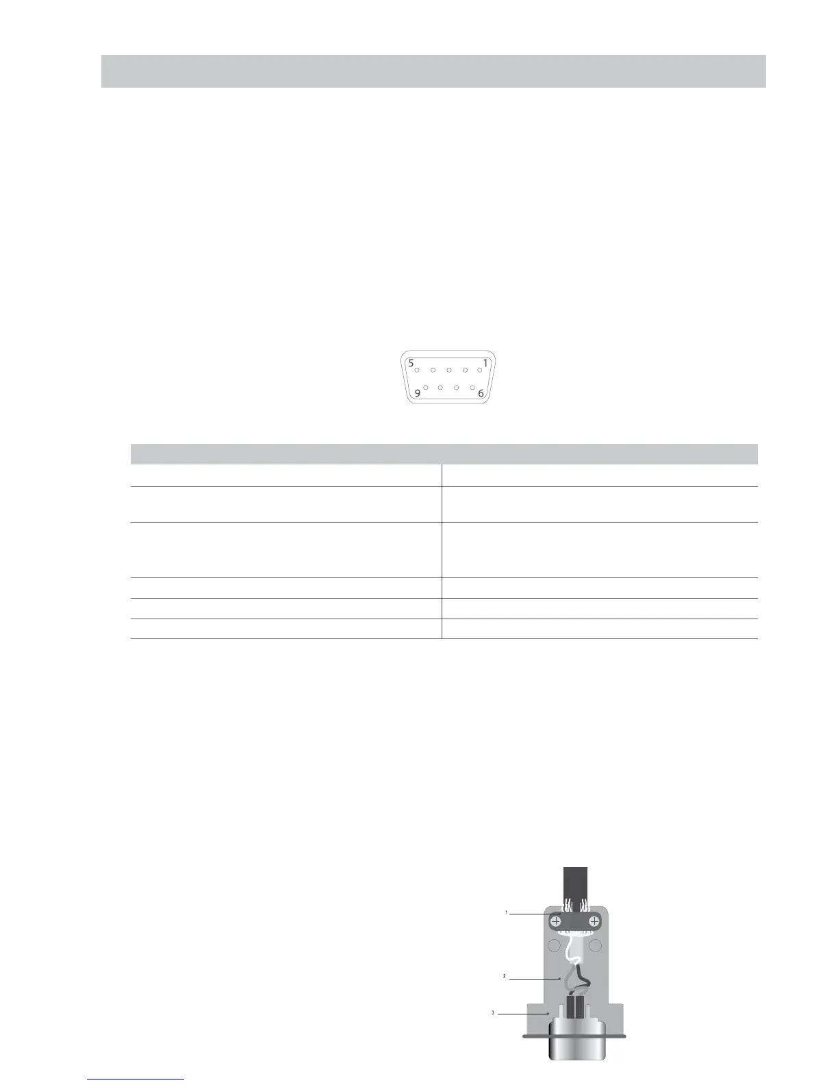
In the figure 7 it is indicated the topography of the connector; the pins have the following functions:
Fig. 8 - Delta connector 9 tracks for the LOAD CELL(S) ENTRANCE
FUNCTION PIN IN C.D.C.
N° PIN NAME FUNCTION N°PIN NAME FUNCTION
1 -EXC (- EXCITATION) 4 +SENSE (+ TERMINAL OF CORREC-
TION)
2 -SENSE (- TERMINAL OF
CORRECTION)
5 +EXC
(+ EXCITATION)
3 GND_A (ANALOG MASS) 6
NOT CONNECTED
7 -OUT (- TRANSDUCER SIGN) 9 NOT CONNECTED
8 +OUT (+ TRANSDUCER SIGN)
If the transducer includes a connection cable with 4 wires plus protection, and not with 6 wires plus protection, the excitation (+) of the device
must be connected with SENSE (+) and the excitation (-) with SENSE (-) joining the pin 1 with the pin 2 and the pin 4 with the pin 5.
To reduce the electrical and radio interferences to the minimum , all the connection cables between the device and the transducer must be of a
protected type, and all the system must be connected to an optimal earth wire.
The supplying company of the device can supply a type of connection cable that was made on purpose for such conditions. This cable includes
a double protection to be welded to the terminals of the shield or on earth.
The following figure shows the different parts involved in the connection of the shields of protection of the cable.
Impedancia mínima 25 Ω
Impedancia máxima 1100 Ω
1 External protection of the cable. It must be pressed in the
metal box for cables with terminal moustaches which must
be tightened between the two lids of the coverage
2 Ending of the internal protection of the cable. It must be
closed in the metal box for cables of the NB. Protection: Do
not connect to the pin 3 of the connector
3 Coverage protected with conductive material