Rev.: 4, Print date: 2021-05-05
16
NL95
1
3
L
N
1
3
L
N
Power Supply module
ITNSLP-01P, 230 V ac (115 V ac)
5
6
1
2
7
2. MAIN
3
8
2. SPARE*
4
910
12
3. MAIN
3. SPARE*
* For ITNL-10-D modules
** Depend on light type
Power Supply module
ITNSLP-01P, 24 V dc
PE**
1
2
PE
MAIN
SPARE
3
4
PE
1
2
PE
MAIN
SPARE
3
4
PE
PE**
PE
PE
1
2
3
4
PE
PE
12
+
-
MAIN
POWER SUPPLY
3
4
+
-
EMERGENCY
POWER SUPPLY
PE
16 mm2
MAIN
POWER SUPPLY
EMERGENCY
POWER SUPPLY
PE
16 mm2
PE
16 mm2
Before connecting, check power supply rating as well as Power Supply module voltage rating
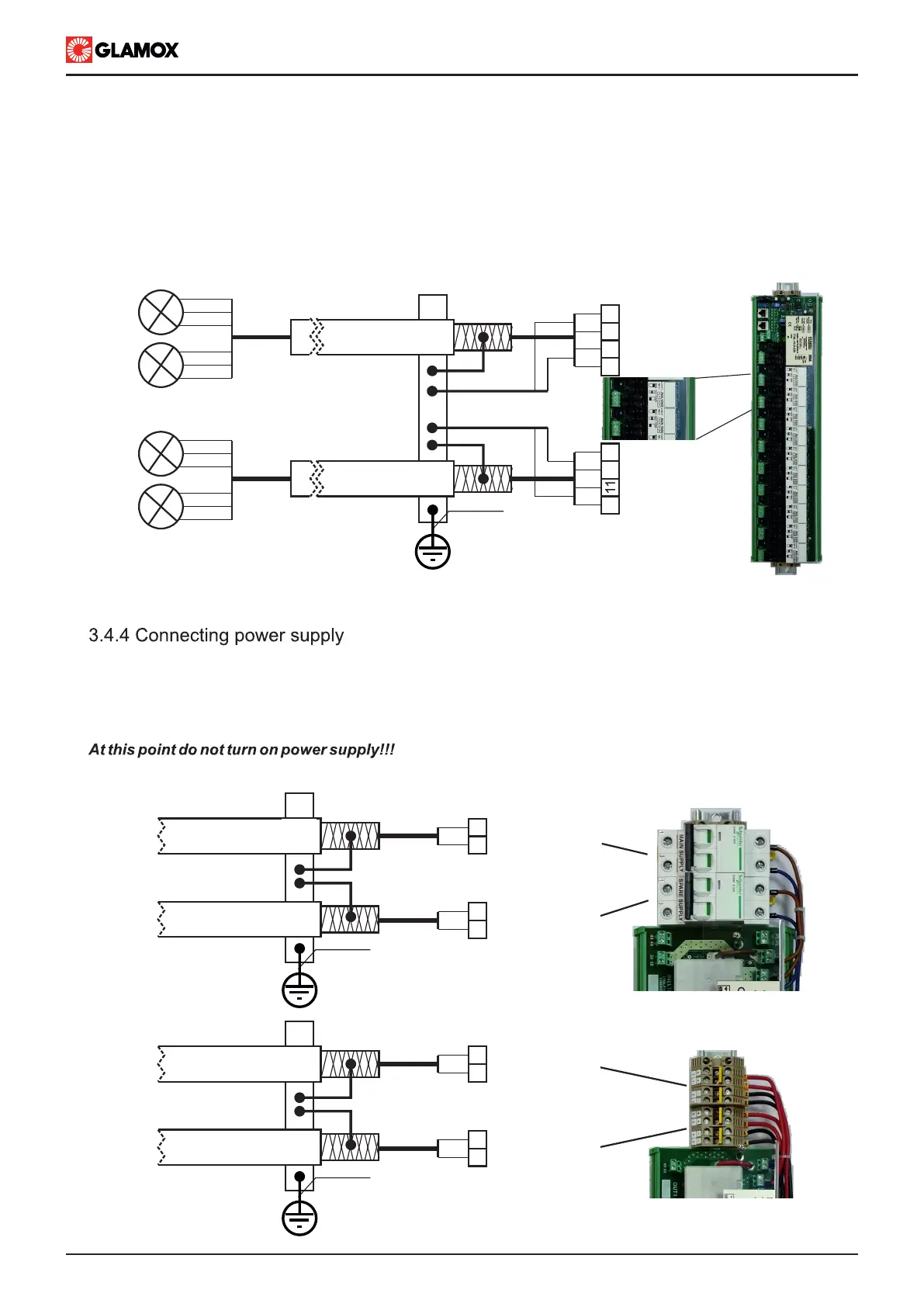
3.4.3 Connecting lights circuits
IMPORTANT!!! Requirements of used navigation and signal lights, and Navigation and Signal Lights Controller
need to be considered. Navigation and signal lights operating manual should be read before continuing.
Navigation and signal lights should be connected according to the prepared connection drawings. Each light
must be connected to appropriate input. Connect cable sheild to equipotential bonding circuit. Wire size to be
according to light requirements. After connecting, mark lable with appropriate lights’ name.
Navigation and Signal Lights Controller power supply should be connected according to prepared connection
drawings. Power supply wires / cables need to be in accordance with systems’ power consumption.
Connect cable shield to equipotential bonding circuit.
Shown 230/115 V ac
module
 Loading...