Rev.: 4, Print date: 2021-05-05
45
NL95
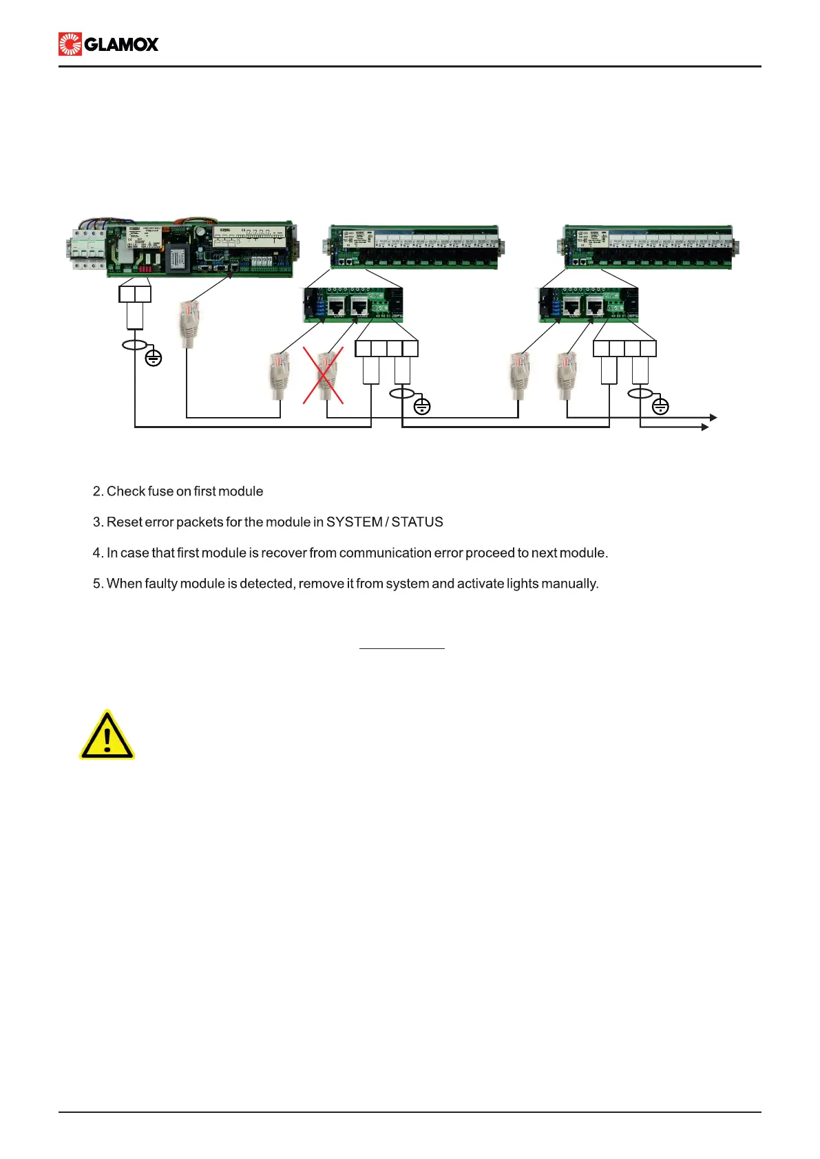
B) In case that all modules are not responding ( all modules have communication error)
In order to find module that “blocks” communication follow instructions below:
1. Disconnect RJ45 connector between first Input module and second Input module as shown bellow.
Light failure
ITNSL detects light faiulre by monitoring current lights circuit. When current drops bellow limit it activates
alarm.
IMPORTANT!!!
Even though light failure is indicated, power supply can be still present on terminals.
Switch off light on main unit and check if power supply is present on light circuit.
1. Check lights fuses
2. Before replacing fuses check lights circuit for short circuit/earthning (do not connect lights if lights cables are
in short circuit or have earth fault).
3. Check light
4. Replace fuses
5. Switch on light
6. Visually check operation of light
In case that light is still not operating, light input circuit is damaged. Connect light to free input and reconfigure
system.
CON3
CON2
CON1
CON2
CON1
TO
NEXT
UNIT
50 51
50 5150
51
50 5150
51
L
N
L
N
L
N
L
N
L
N
CON1 CON2
MAIN UNIT
ITNSL-01TP
CON1 CON2
CON3
AUDIO ALARM ACCEPT INPUT
AL2
2 3 4 5 6 7 8 9 10 12 13 14 15 161
AL1 AL3SYS
C.O. VOLTAGE-FREE OUTPUT CONTACT
18 19 2017 21
SYSTEM OPERATING
COMMON ALARM OUTPUT
B A B A
-
RX TX
NMEA 0183
RECIEVER
NMEA 0183
TRANSMITTER
CON3
INPUT
MODULES
Shown 230/115 V ac modules