Rev.: 4, Print date: 2021-05-05
11
NL95
Allow sufficient clearance of 20 mm around modules
Switches for manual activation, fuses and labels should
be clearly visible and accessible.
Console
Main
unit
Main unit cable -
original cable
2.5 m long
Power
Supply
module
Input
modules
Cable trays
Input module cable -
original cable
1.5 m long
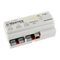
Power Supply and Input modules
Allow suficient clearance around modules for mounting and for the connection of cables and wires.
Minimum distance 20 mm around modules. It is not recommended to route light cables together with power
cables.
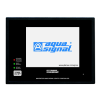
Allow sufficient clearance around main unit for mounting as well as connection of cables and wires.
Minimum distance (x = 40 mm; y=40 mm; z=150 mm)
Do not install main unit near power cables!!!
It is not recommended to install main unit on direct sunlight.
The material in the area of the mounting cut-out must provide
sufficient strength to guarantee the enduring and safe mounting
of the main unit.
The force of fixing nut or operation of the main unit
must not lead to deformation of the material.
Main unit
Keep the supplied documentation and configuration file in a safe place. The documents belong to the
Navigation and Signal Lights Controller may be required for subsequent commissioning.
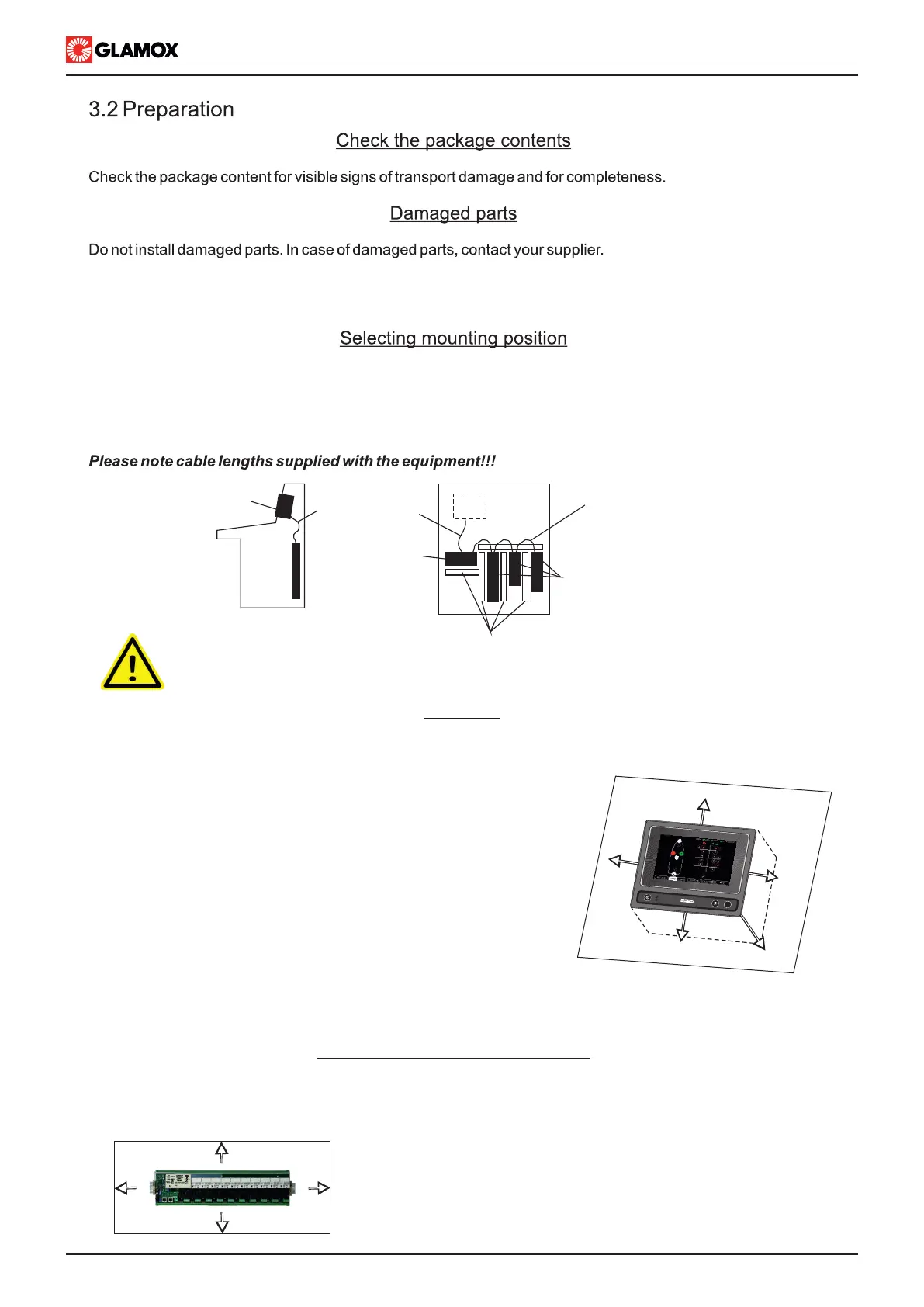
Navigation and Signal Lights Conroller needs to be installed on the bridge, Main unit should be installed on
console in accordance with guidance notes on ergonomic desgin and navigation bridges. Power Supply
and Input modules needs to be installed inside console. Modules need to be easily accessible for manual
operation of lights. Preferable arrangment shown in figure below:
x
x
y
y
z
POWER ON
FAILURE
F1
Main unit, Power Supply module, and Input Modules should have compass clearance of
minimum 85mm distance in all directions.