Rev.: 4, Print date: 2021-05-05
48
NL95
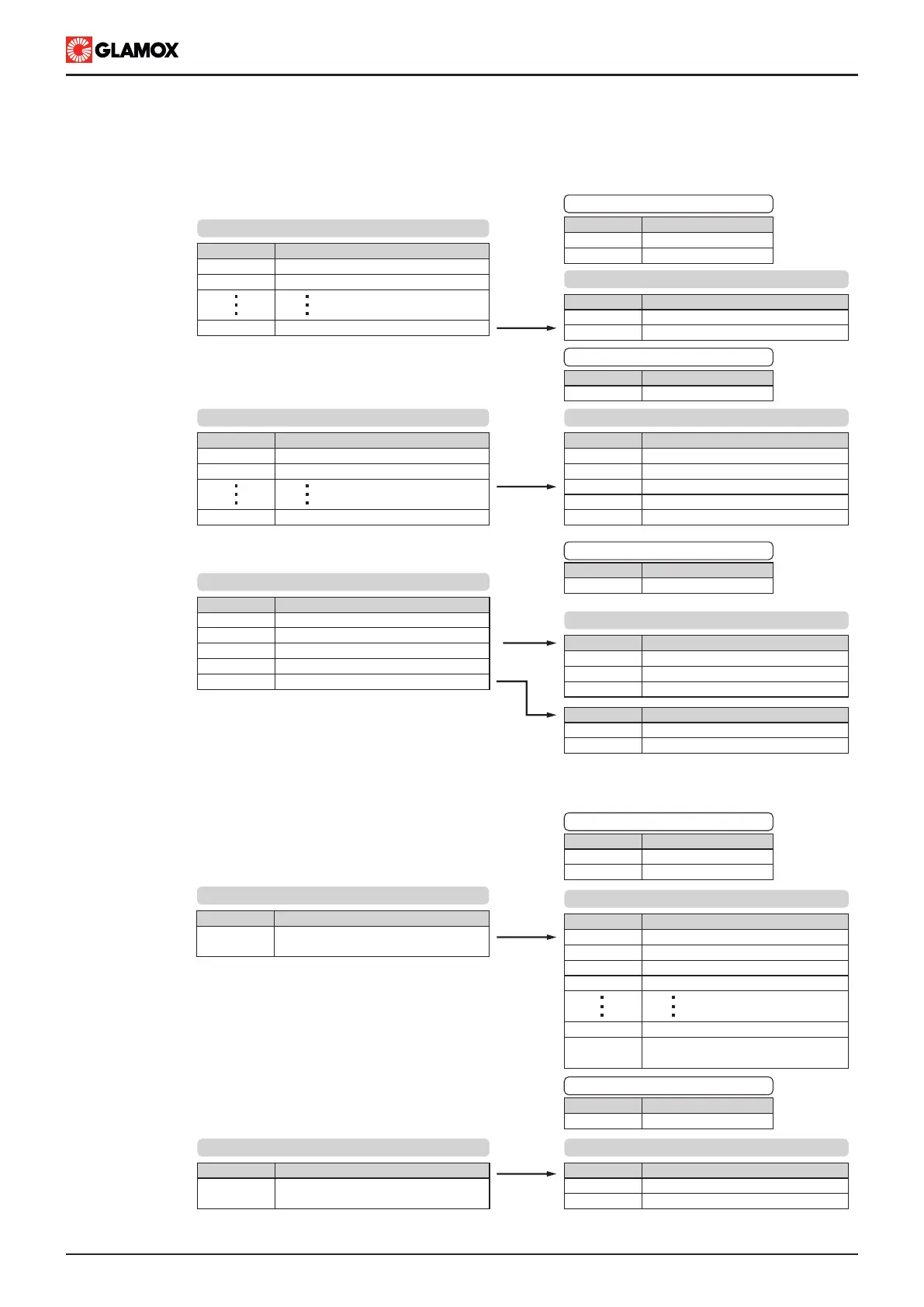
1. LIGHTS CONTROL*: Turn on/off of each individual light
Description:
Turn off light
Turn on light
Value
0
1
Light control value:
2. LIGHTS STATUS: Read status of each individual light
Name:
read holding registers
Code
03
Supported modbus functions:
Description:
Light not present or not connected
Light off
Light main on
Light spare on
Light alarm
Value
0x0000
0x0001
0x0002
0x0003
0x0004
Light status value:
Name:
write single coil
write multiple coils
Code
05
15
Supported modbus functions:
Configured lights in ITNSL-01TP:
Light no. 1
Light no. 2
Light no. 199
Address
00001
00002
00199
Address range:
4. GROUPS CONTROL*: Turn off all lights at once,
and turn on only the lights associated with configured group.
This command relftects, if turned on lights belongs to predefined
group.
Name:
read holding registers
write single register
Code
03
06
Supported modbus functions:
Configured groups in ITNSL-01TP:
Turn off all lights /or turn on only one
configured group
Address
40205
Address range:
Address range:
Description:
Turn off lights /or All lights is OFF
Turn on Group no. 1
Turn on Group no. 2
Turn on Group no. 3
Turn on Group no. 40
(Read only) turned on light/s does
not belong to any group
Value
0x0000
0x0001
0x0002
0x0003
0x0028
0xFFFF
Group control value:
5. ALARM ACCEPTANCE: Mute external alarm output,
and acknowledge of all
current alarms.
Name:
write single register
Code
06
Supported modbus functions:
Description:
Mute / acknowledge of current
system and/or lights alarms
Address
40206
Address range:
Description:
Mute
Mute and acknowledge alarms
Value
0x0001
0x0002
Alarm acknowledge value:
3. SYSTEM STATUS :
Description:
(1)
Common alarm
(2)
Lights alarm
(3)
Power supply alarm
(4)
Module communication alarm
Modbus RTU write
Address
40200
40201
40202
40203
40204
Address range:
Description:
Status OK
Alarm exists
Alarm acknowledged, and exists
Value
0x0001
0x0002
0x0003
Alarm acknowledge value:
(1) Common alarm flag summarizes all light, main and spare power
supply, and modules communication alarms
(2) Lights alarm indicates one or more lights contain alarms
(3) Power supply alarm indicates main or spare power supply contain
alarm
(4) Module alarm indicates one or more modules contain alarm, user
should acknowledge alarm from main unit ITNSL-01TP
Name:
read holding registers
Code
03
Supported modbus functions:
Configured lights in ITNSL-01TP:
Light no. 1
Light no. 2
Light no. 199
Address
40001
40002
01994
Description:
Disabled
Enabled
Value
0x0000
0x0001
* IMPORTANT! User should take care when using Lights
control and groups control in the same system, ITNSL-01P
software will process last command recieved.
}
9.3 Remote Control MODBUS RTU protocol supported parameters
Depending on installed hardware, modbus interface connection support data over TCP/IP, RS485, or RS232.
- TCP/IP is user configurable
- RS485, and RS232, ordered as option with code 02-04-227, support fixed baud rate 9600 8N1