Rev.: 4, Print date: 2021-05-05
43
NL95
8. Troubleshooting
In order to detect problem and solve it, please follow instructions in this section. In case that your problem is
not described, contact your sales representative for more assistance.
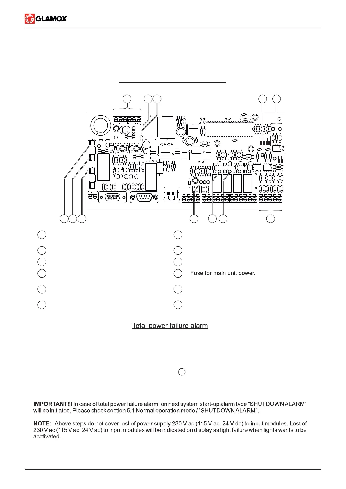
For easier check up of system, please check bellow overview of Power Supply module PCB.
93CON1 CON2
RX1TX1
SYS
CON3
AL1 AL2 AL3
TX2
EMERG
ADDRESS
DISP
MAIN
10
1
1112 9
TERM
ITNSLP-01P
MC E + - PE
2 3 5
IN1 IN2 IN3
8 7
4
1 2 4 5 6 7 8 10 111213141516 1718192021
6
1 7
82
93
104
5
6
Power input for modules “+, -” terminals,
19V dc up to 32V dc
SYS LED, System operating indication
Main power supply LED indication
TX2 LED, NMEA communication
blink approx 10sec.
RX1, TX1 LEDs, communication between
Power Supply module and main unit
Fuse for internal power supply
11
IN1, IN2, and IN3 LEDs indications
Emergency power supply LED indication
NMEA Terminals
AL1 LED, Common Alarm indication
DISP LED, power 24Vdc to main unit
present
12
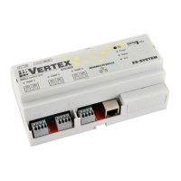
ITNSLP-01P power supply module
Due to batteries inside Power Supply module power failure alarm can be indicated without any of other equipment
connected to Main unit. In order to determine fault in system power supply please follow steps bellow:
1. Check power supply to Power supply module, main and emergency LEDs
2. Check connection between Main unit and Power Supply module
3. Check fuse 3.15AF and 2AF on Power Supply module
5. Measure 19 V dc - 32Vdc voltage between + and -
6. Check fuse F2 on Power Supply module (applicable for ITNSLP-01P 230 V ac and ITNSLP-01P 115 V ac)
7. Check fuse F1 on Power Supply module
1