Rev.: 4, Print date: 2021-05-05
12
NL95
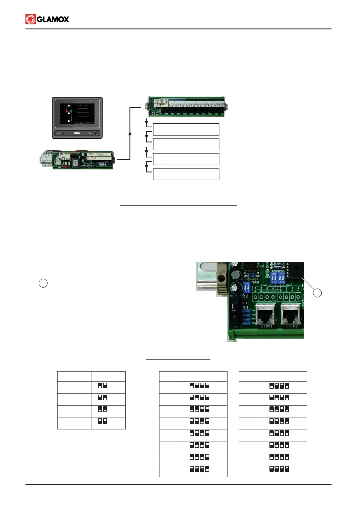
Arrangement
Following arrangement of Input modules needs to be followed:
- Up to 5 Input modules (in total) can be installed
- Up to 3 pcs ot ITNL-10-D or ITNL-5-D (double lights)
- Up to 5 pcs of ITNL-10-S or ITNL-13-S (single lights)
- ITNL-10-D and ITNL-10-S can be combined in the same system
- Maximum number of lights : 80 ( in configuration: 30 double lights and 20 single lights)
ITNL-10-D or ITNL-10-S,
Address 1
ITNL-10-D or ITNL-10-S,
Address 2
ITNL-10-D or ITNL-10-S,
Address 3
ITNL-10-S,
Address 4
ITNL-10-S,
Address 5
Input module ITNL address selection
ITNL Input module address is configurable by dip switches located on module
1- Address selection should be done when module is not connected, or system is powered off
2- Module addresses must not be duplicated.
When addressing please consult with prepared connection diagram.
This applies to 230 V ac, 115 V ac as well as 24 V dc ITNL modules.
ITNL address tables
Module type ITNL-10-D
MODULE
ADDRESS
1
2
3
4
1 2
ON
OFF
1 2
ON
OFF
1 2
ON
OFF
1 2
ON
OFF
DIP
SWITCH
Module type ITNL-10-S / ITNL-5-D / ITNL-13-S
MODULE
ADDRESS
1
2
3
4
5
6
7
8
1 12 24 48 8
ON ON
OFF OFF
1 12 24 48 8
ON ON
OFF OFF
1 12 24 48 8
ON ON
OFF OFF
1 12 24 48 8
ON ON
OFF OFF
1 12 24 48 8
ON ON
OFF OFF
1 12 24 48 8
ON ON
OFF OFF
1 12 24 48 8
ON ON
OFF OFF
1 12 24 48 8
ON ON
OFF OFF
DIP
SWITCH
DIP
SWITCH
MODULE
ADDRESS
9
10
11
12
13
14
15
16
1
1
Adjust address of module,
- each module should have unique address
- use one of the combination in the table below
Module configured with address 16 shown in the photo
CON1 CON2
MAIN UNIT
ITNSL-01TP
CON1 CON2
CON3
AUDIO ALARM ACCEPT INPUT
AL2
2 3 4 5 6 7 8 9 10 12 13 14 15 161
AL1 AL3SYS
C.O. VOLTAGE-FREE OUTPUT CONTACT
18 19 2017 21
SYSTEM OPERATING
COMMON ALARM OUTPUT
B A B A
-
RX TX
NMEA 0183
RECIEVER
NMEA 0183
TRANSMITTER
CON3
INPUT
MODULES
Shown 230/115 VAC modules
POWER ON
FAILURE
F1
 Loading...