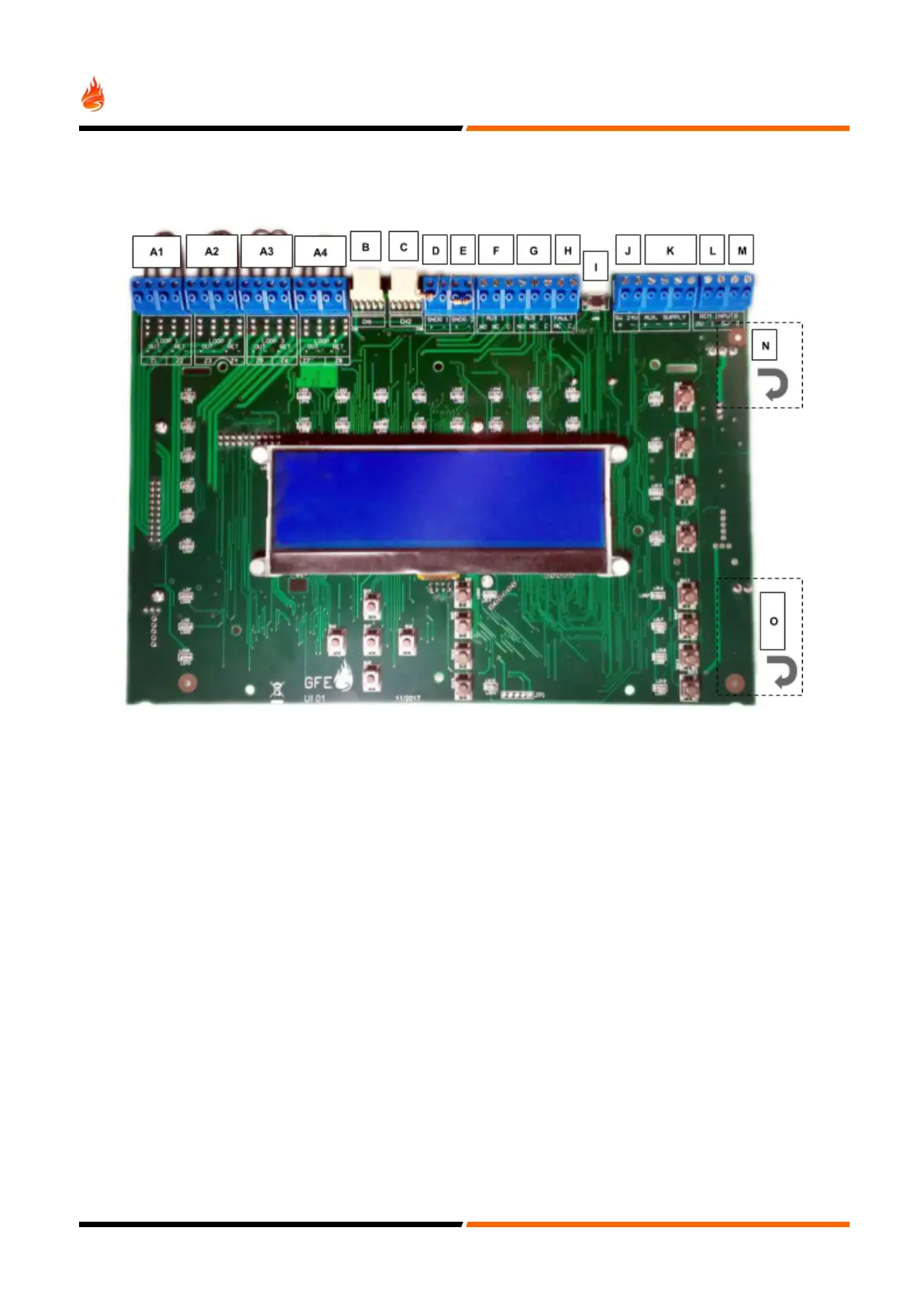
GEKKO Main Board
A - Loop connections. A1 corresponds to Loop 1, A2 to Loop 2, A3 to Loop 3 and A4 to Loop 4
B - Communication channel (CH1)
C - Communication channel (CH2)
D - Conventional sounder circuit 1
E - Conventional sounder circuit 2
F - Auxiliary change-over relay output 1(Activated by any fire present on the system, disabled by front button)
G - Auxiliary change-over relay output 2 (Activated by any fire present on the system, disabled by front button)
H - Fault NC relay contact (Activated by any fault present on the system, opens on fault)
I - MICRO USB Connector
J - Switched 24V auxiliary power supply (switches off, for 15 seconds @ every reset event)
K - 24V auxiliary power supply output for powering external devices.Max 300mA power limited and monitored
L - Remote disablement of selected detectors
M - Remote Evacuation or Class Change
N - System power input
O - 24V battery connection
14
 Loading...