Vehicle Equipment Installation Instructions 8
3 Description
This section provides a general description of the
Opticom™ GPS system and a detailed description
of the vehicle equipment.
3.1 Opticom™ GPS System
The Opticom GPS system assists authorized
priority vehicles through signalized
intersections by providing temporary right-of-
way through the use of common traffic
controller functions.
The Opticom GPS system consists of the
following matched components:
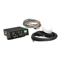
Vehicle Equipment —
Radio/GPS unit containing a GPS receiver and
a 2.4 GHz transceiver
Radio/GPS antenna
Control unit
Intersection Equipment —
Radio/GPS unit containing a GPS receiver
with antenna and a 2.4 GHz transceiver with
antenna
Or Radio/GPS unit containing a GPS receiver
and a 2.4 GHz spread spectrum transceiver
with a separate Radio/GPS antenna
Phase Selector
Card Rack/Input File
Auxiliary Interface Panel
Auxiliary Harness
The vehicle equipment is mounted on the priority
vehicle. Its GPS receiver acquires position
information from the constellation of GPS
satellites. This information is used to compute the
location, speed, and heading of the vehicle. This
information, along with a priority request and the
state of the vehicle’s turn signal, is broadcast using
the 2.4 GHz transceiver.
The intersection equipment receives the radio
transmission from the vehicle equipment. The
intersection equipment then compares the
information being received from the vehicle to
the parameters stored in the intersection
equipment’s memory. If the vehicle is heading
toward the intersection in a predefined
approach corridor, is requesting preemption and
has met all other programmed parameters, the
corresponding phase selector output is
activated. This output is connected to the traffic
controller preemption input. When activated,
the controller cycles to grant a green light to the
requesting vehicle or holds the green allowing
the vehicle to pass through the intersection.
The card rack/input file provides the power and
logic wiring for the phase selector, which plugs
directly into a slot in the unit.
The auxiliary interface panel provides additional
connections for monitoring green phases and
also provides additional priority control outputs.
The green sense harness can be used to provide
additional connections for monitoring green
phases when the auxiliary interface panel is not
required.