Vehicle Equipment Installation Instructions 15
5.4 Radio/GPS Unit Cable Terminations
1. Route the cables from the radio/GPS antenna
through the vehicle to the radio/GPS unit
location.
2. Coil up any excess cable.
Note: When coiling excess cable do not
create any sharp bends in the cable or the
cable may be damaged.
3. Connect the cable labeled GPS to the GPS
connector on the radio/GPS unit. Connect the
other cable to the Radio connector. Tighten
the connectors using a 5/16” wrench (an 8
mm wrench may also be used).
Note: The connectors are keyed and cannot
be connected to the wrong connector.
Note: To avoid damage to the equipment
always connect the GPS and Radio
connectors before connecting the radio/GPS
cable. Never operate the equipment with
the antenna cables disconnected.
Also be sure that the end of the radio/GPS
cable that connects to the Vehicle control
unit is plugged in AFTER the 15-pin
connector is plugged into the radio/GPS
unit.
4. Plug the 15 pin connector of the radio/GPS
cable (black cable) into the P1 connector of
the radio/GPS unit and tighten the screws.
5. Route the cable to the location where the
Vehicle Control unit will be installed.
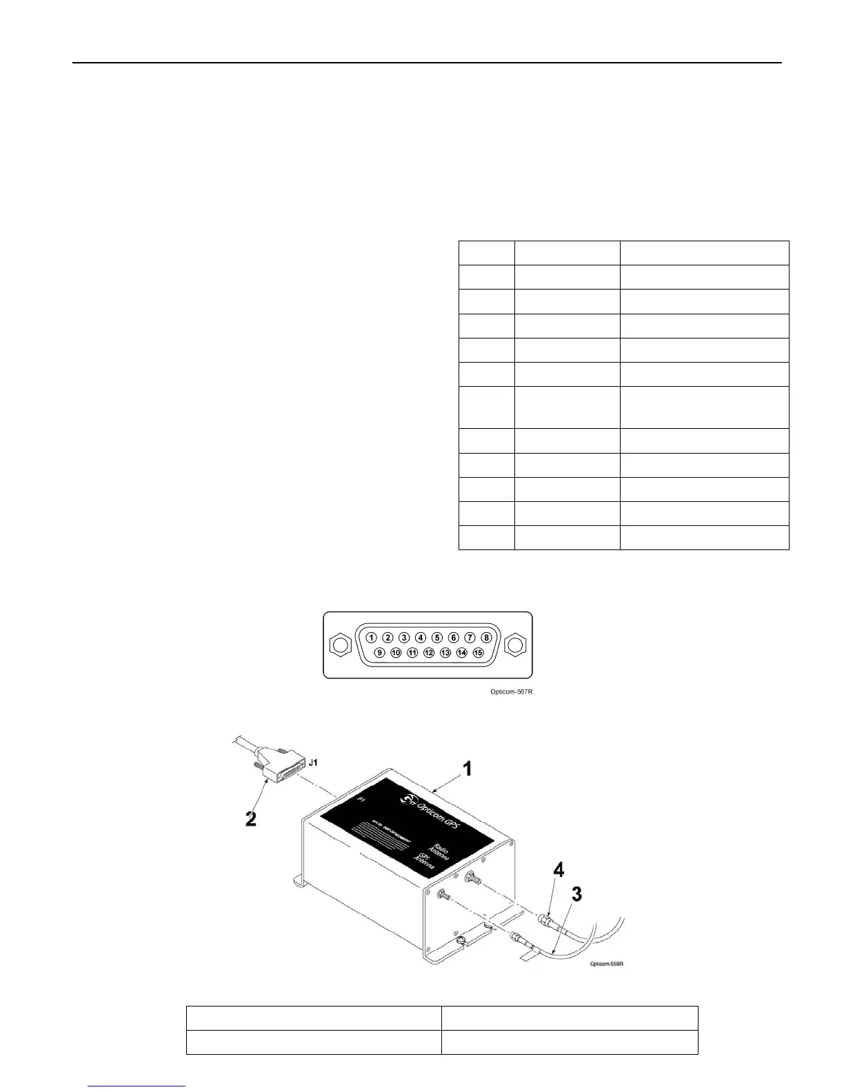
Table 5-1. Radio/GPS Cable Connector Pin
Index
Pin Wire Color Function
1 Yellow Radio transmit (+)
2 Yellow Black Radio transmit (–)
4 Blue Radio receive (+)
5 Blue White Radio receive (–)
7 Orange Radio clock (+)
8 Orange
Green
Radio clock (–)
9 Brown GPS power
11 Brown White Common
12 Violet White Common
13 Bare Shield drain wire
15 Violet Radio power
Figure 5-4. Radio/GPS Cable Connector Pin Configuration
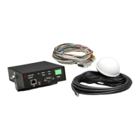
Figure 5-5. Radio/GPS Cable Installation
1. Vehicle radio/GPS unit 3. GPS antenna cable
2. Radio/GPS cable assembly 4. Radio antenna cable