Vehicle Equipment Installation Instructions 13
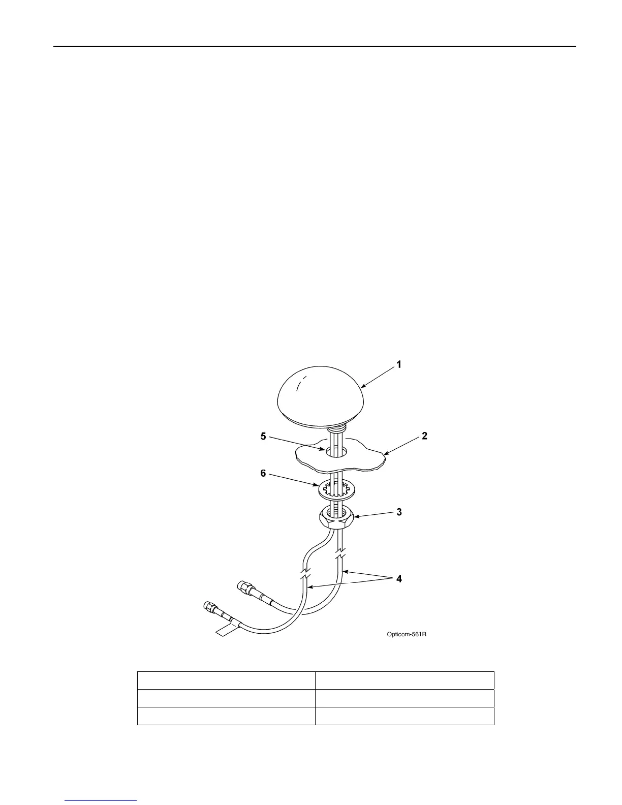
5.2 Model 1050 Radio/GPS antenna
installation
1. Remove the nut and washer from the
Radio/GPS antenna.
2. Drill a 5/8 to 3/4-inch hole. See Figure 5-2.
3. Route the cables through the hole. And
replace the lock washer and nut.
4. Tighten the nut with a15/16” wrench (a 24
mm wrench may be used if a 15/16’ wrench is
not available)
Note: Do not over tighten the nut or the antenna
may be damaged. 5 ft/lbs is the recommended
torque.
5. Apply silicone RTV (not provided) around the
antenna if the roof curvature prevents a good
seal with the antenna’s built-in gasket.
6. If necessary alternate mounting brackets are
available for mounting on vehicle mirrors,
vertical posts and trunk lids. These brackets
are available from Mobile Mark
Communications Antennas
(www.mobilemark.com, 1-800-648-2800).
The part numbers are SM-MM (mirror mount)
and SM-TM (trunk lid mount). When using
these mounts, GTT recommends that the
bottom of the antenna where the cables exit
be sealed with RTV. Also care should be
taken to protect the cables where they enter
into the vehicle.
7. An adapter for thicker roofs is available.
Contact GTT Technical Service at 1-800-258-
4610 for details.
Figure 5-2. Mounting Radio/GPS Antenna on Priority Vehicle
1. Vehicle radio/GPS antenna 4. Radio and GPS antenna cables
2. Vehicle mounting surface 5. 5/8 to 3/4-inch mounting hole
3. Antenna nut 6. Antenna lock washer