24 Vehicle Equipment Installation Instructions
Table 7-2. Expected Voltages
Location/Terminal Expected Voltage Notes
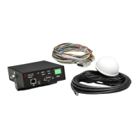
Red to Black wires on harness 12 VDC Check fuse.
Blue wire on harness 12 VDC Must have 12 VDC to activate
system, check fuse.
Brown to Brown/White Approximately 7.15 VDC GPS power source, check for at
least 5 seconds.
Violet to Violet/White Approximately 7.75 VDC Radio receiver power source,
check for at least 5 seconds.
8 Maintenance
Opticom™ GPS system components are
designed for reliable operation. Inspect the
components at regular intervals to ensure proper
system operation.
GTT recommends the following:
Each intersection system and vehicle system
should be inspected and tested at least every
12 months to ensure it functions to your
specifications and requirements.
Intersection systems should be tested with
known good vehicle systems.
Vehicle systems should be tested with known
good intersection systems.
You should develop a test plan that fits your
department’s operations and meets the needs
of your system.
You should keep accurate and up-to-date
records of system performance and test
results.
Note: When washing the vehicle, avoid pointing
a high-pressure washer at the radio/GPS antenna.