Vehicle Equipment Installation Instructions
10
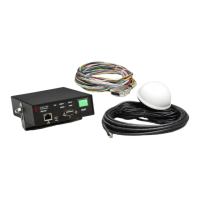
3.3 Parts List
The following is a list of components in the vehicle
kit. See Figure 3-1 for more details.
1 Model 1050 Radio/GPS antenna
White 3” diameter dome with two 15’
cables.
4 Model 1020 or 1021 Vehicle Control Unit (VCU
Black module with ON/OFF switch and
indicators
Mounting bracket and screws.
10 Model 1012 Radio/GPS unit
Aluminum module with mounting
screws
11 Model 1071 Vehicle Interface Harness
15’ Cable with a DB-15 connector and
15’ of un-terminated loose wires
12 Model 1072 control unit cable assembly
20’ Cable with a DB-15 connector
and a black cable
Miscellaneous parts
Two fuse holders
Two 2 amp fuses
Two fuse labels
Two Grommets
Installation Instructions
4 Features
Opticom™ GPS system vehicle equipment has the
following features:
Vehicle identification encoding; selectable at
installation
User-selectable Disable mode; Latching or
Non-Latching modes
Diagnostic indicators
Millions of vehicle identification codes
Agency ID capability
Wide operational temperature range:
–30°F to +165°F (–34°C to +74°C)
Meets FCC part 15 Class A specifications
Additional GPS output in NMEA format for
other onboard uses
R5485/J1708 serial interfaces
15 & 20-foot cables for installation flexibility
Available Windows™
*
Configuration and
Maintenance Software
*
Windows is a trademark of Microsoft Corporation.