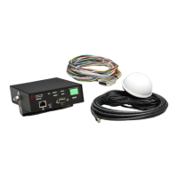
Vehicle Equipment Installation Instructions
24
7 Troubleshooting
Table 7-1 shows the symptoms of
the Opticom™ GPS System Vehicle
Equipment installation problems. The table
also shows the possible causes of those
problems and suggests solutions to correct
them.
Table 7-2 shows the expected voltages at various
wiring terminals.
Table 7-1. Troubleshooting Symptoms, Possible Causes, and Solutions
Symptom Possible Cause Solution
Vehicle control unit POWER LED
will not light.
Wiring incorrect. Check wiring. Verify that control
unit is getting 12 VDC.
Remote activation line not active. Verify that 12 VDC is being
applied to blue wire of vehicle
interface harness.
Fuse/s blown Replace fuses with 2A/250V 3AG
SLO-BLO.
Vehicle control unit failed. Return unit to GTT for service.
Times in log are incorrect. Time localization not set, or set
incorrectly.
Set correct time zone for your
area.
GPS will not acquire.
(GPS LED is amber.)
Initial start-up may take up to 15
minutes.
Wait 15 minutes.
Radio/GPS unit’s view of sky is
obstructed.
Move unit or remove obstructions.
RF interference. Turn off vehicle control unit for
15 minutes, then try again.
Incorrect wiring. Check wiring at both ends of
radio/GPS cable.
Radio/GPS cable connector
(terminal block) plugged in
backwards.
Plug in terminal block correctly.
Radio/GPS unit failed. Return unit to GTT for service.
Radio/GPS antenna failed. Return unit to GTT for service.
Vehicle control unit failed. Return unit to GTT for service.
No power to GPS receiver. Check voltage between brown (+)
and brown/white (–) wires at both
ends. It should be about 8.3
VDC.