Vehicle Equipment Installation Instructions 9
3.2 Vehicle Equipment
Please be aware of the following operational
characteristics of this equipment.
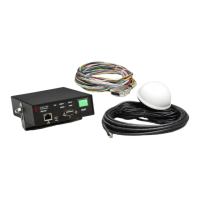
The Opticom™ GPS System vehicle equipment
is intended for use on priority vehicles. The
vehicle equipment consists of a radio/GPS unit
containing a GPS receiver and a 2.4 GHz
transceiver, a radio/GPS antenna, as well as a
control unit, which also provides an interface
point between the radio/GPS unit, the vehicle
wiring, and an external PC used for configuration
and diagnostics.
Appropriate agency ID, vehicle class, and
vehicle ID numbers are determined at the time of
installation and are programmed by the user via
configuration software.
The Disable feature uses an additional switch
(customer supplied) that connects to battery
negative or positive when actuated.
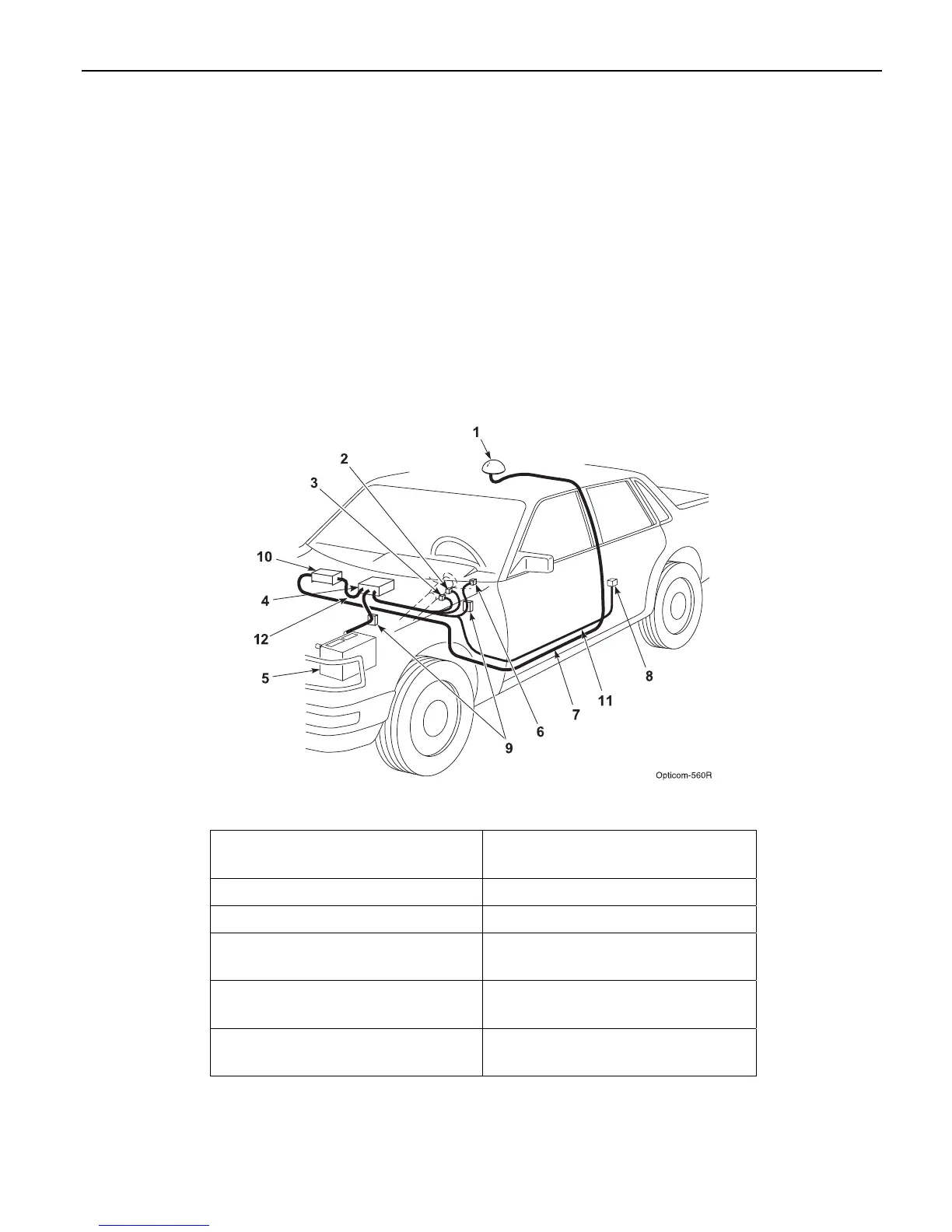
Figure 3-1 shows a typical vehicle equipment
installation for a priority vehicle.
This manual describes how to install the vehicle
equipment.
Figure 3-1. Typical Vehicle Equipment Installation for Priority Vehicle
1. Radio/GPS antenna (Model
1050)
7. Radio/GPS antenna cable
2. Left turn signal sense 8. Disable switch
3. Right turn signal sense 9. Fuses
4. Model 1020-1021 Vehicle
control unit (VCU)
10. Model 1012 Radio/GPS unit
5. Battery 11. Vehicle interface harness
(Model 1071)
6. Light bar sense 12. Control Unit cable assembly
(Model 1072)