Vehicle Equipment Installation Instructions
16
5.5 Vehicle Control Unit Installation
This subsection describes the installation of the
Opticom™ GPS System Vehicle Control Unit.
It also describes connecting the radio/GPS
cable from the radio/GPS unit to the control
unit and connecting the vehicle interface
harness to the control unit.
Please read and fully understand the following
precautionary paragraphs before installing the
control unit.
Installations may include a customer-supplied
disable switch in addition to the control unit.
The Disable feature disables the priority
request when the disable switch closes to
battery negative or positive. This feature
typically uses an existing switch that indicates
the presence of conditions deemed appropriate
to disable the priority request, such as opening
the vehicle operator’s door.
The control unit must not be in the path of
airbag deployment.
Use care when drilling holes to avoid drilling
into undesirable locations.
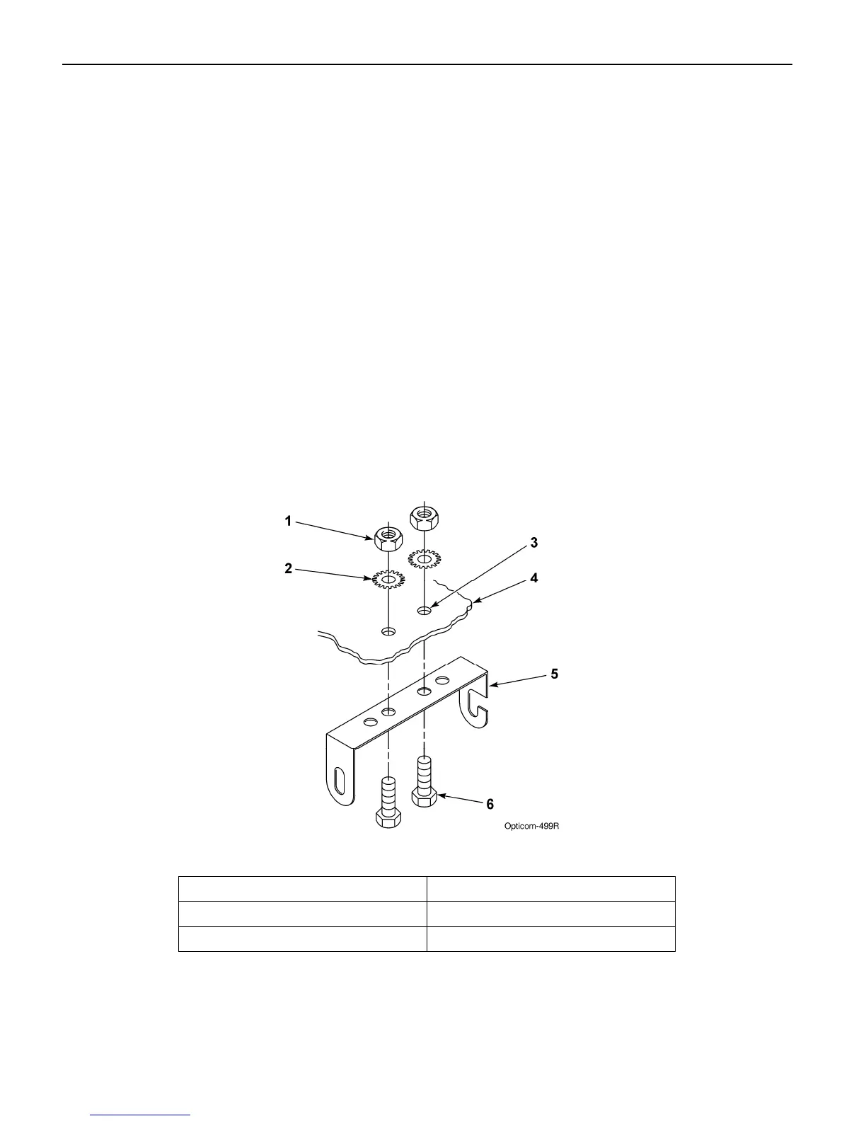
1. Determine the desired location to mount
the vehicle control unit. Mark and drill
two 7/32-inch holes, using the control
unit mounting bracket as a template.
2. Insert the two 10-32 x 3/4-inch cap screws
through the holes in the mounting bracket
and mounting surface. See Figure 5-6.
3. Use the two lock washers and 10-32 nuts to
secure the bracket to the vehicle.
Figure 5-6. Control Unit Mounting Bracket Installation
1. 10-32 nut (2) 4. Mounting surface
2. Lock washer (2) 5. Mounting bracket
3. 7/32-inch hole (2) 6. 10-32 x 3/4-inch cap screw (2)