Vehicle Equipment Installation Instructions
17
4. Cut the Radio/GPS cable (black cable) to the
proper length.
5. Strip approximately 3 inches of the outer
jacket from the end of the cable. Be careful
not to cut the wires inside.
6. Strip 1/4 inch of insulation from each wire.
Note: It is very important not to strip too
much insulation, which may lead to short
circuits; or too little insulation, which may
prevent the wire from making good contact.
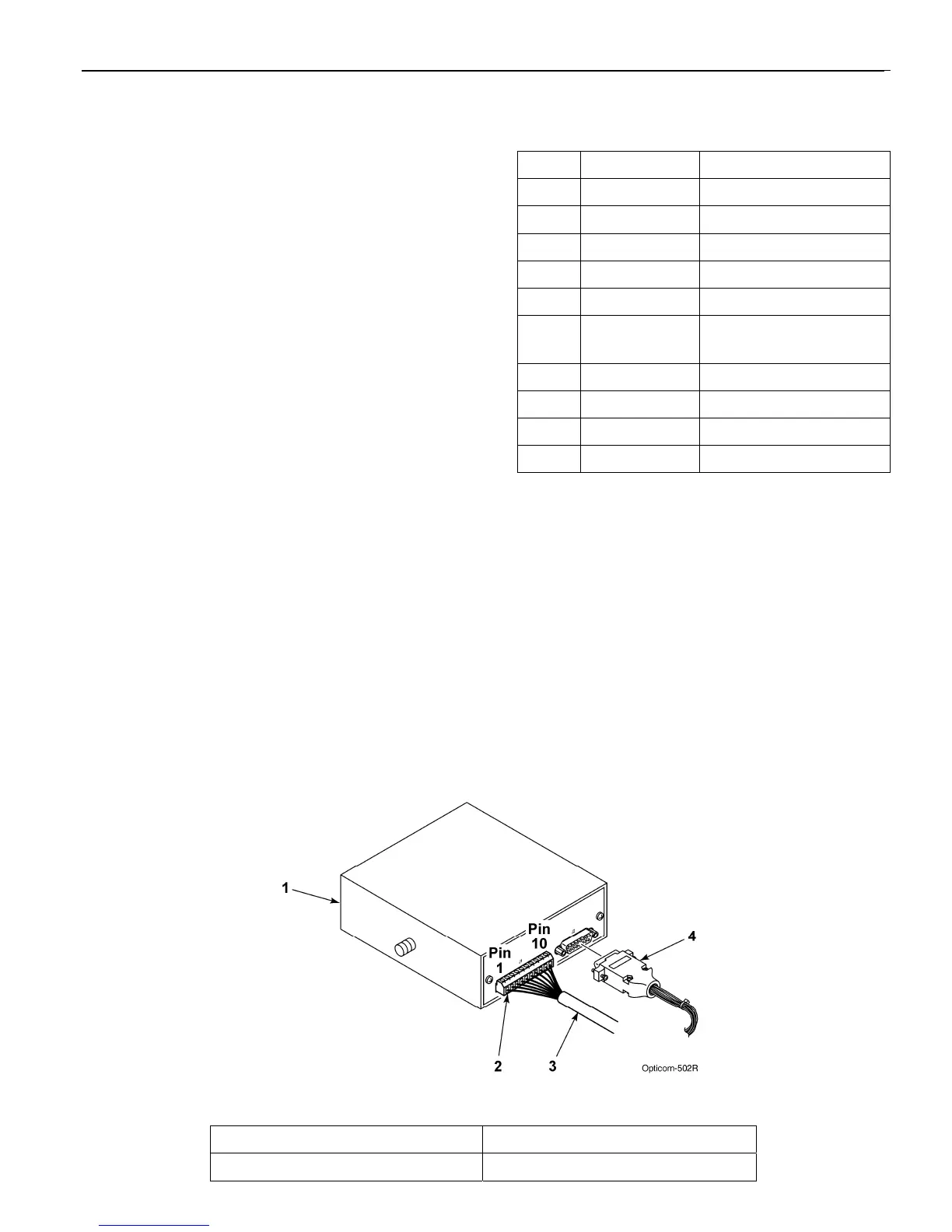
7. Place each wire into the appropriate terminal
in the 10-pin terminal block located on the
back of the control unit and tighten the screw
to secure the wire. The label on the terminal
block shows the color for each wire. Table 5-
2 also shows the terminal block pin number,
wire color, and function for each wire. See
Figure 5-7.
The terminal block may be removed from the
control unit to allow easier connections.
8. Cut the bare wire off even with the edge of the
outer jacket of the cable.
9. Plug the vehicle interface harness into the 15-
pin connector on the back of the control unit
and tighten the screws. See Figure 5-7.
Note: Be sure that the end of the radio/GPS
cable that connects to the Vehicle control
unit is plugged in AFTER the 15-pin
connector is plugged into the radio/GPS
unit.
Table 5-2. Control Unit Terminal Block
Pin Index
Pin Wire Color Function
1 Yellow Radio transmit (+)
2 Yellow Black Radio transmit (–)
3 Blue Radio receive (+)
4 Blue White Radio receive (–)
5 Orange Radio clock (+)
6 Orange
Green
Radio clock (–)
7 Brown GPS power
8 Brown White Common
9 Violet Radio power
10 Violet White Common
Figure 5-7. Vehicle Control Unit Wiring
1. Vehicle control unit 3. Radio/GPS cable
2. 10-pin terminal block 4. Vehicle interface harness