Vehicle Equipment Installation Instructions
18
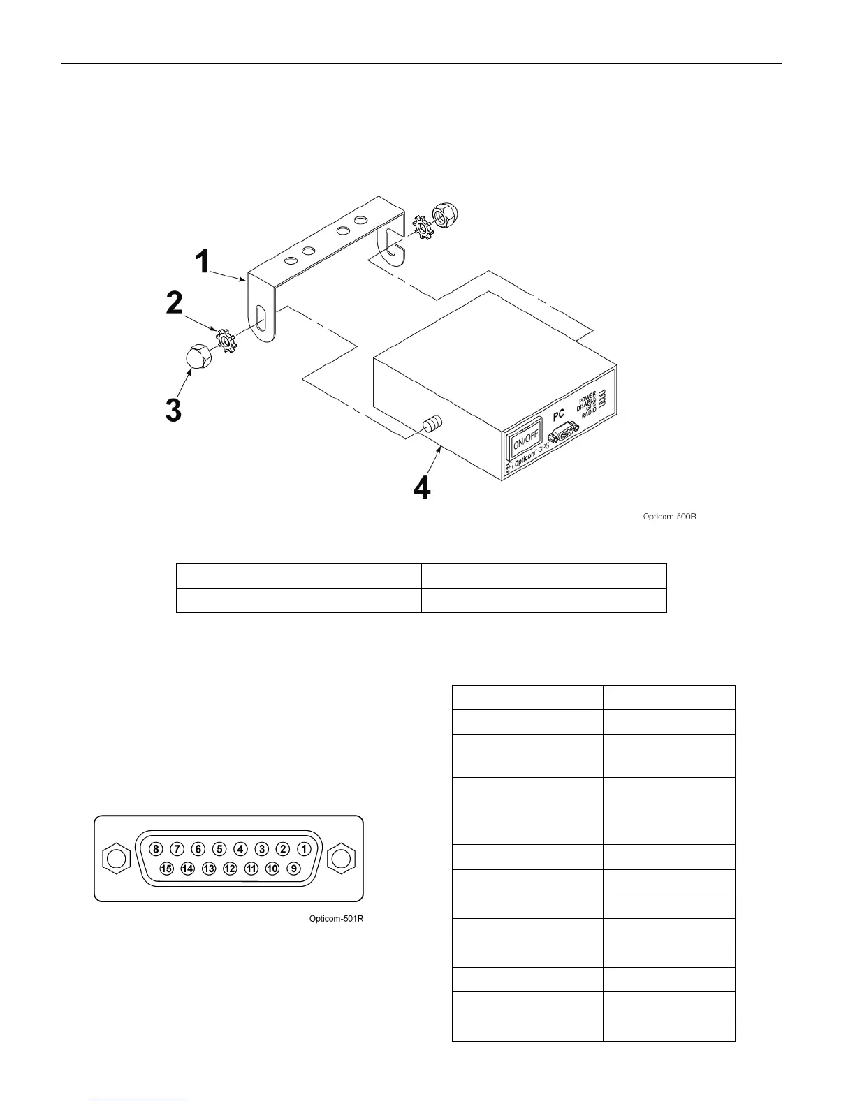
10. Place the control unit into the mounting
bracket. Use the two 1/4-inch acorn nuts
and lock washers to secure the control unit to
the bracket. See Figure 5-8.
Figure 5-8. Vehicle Control Unit Installation
1. Mounting bracket 3. Acorn nut (2)
2. Lock washer (2) 4. Vehicle control unit
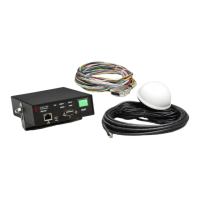
11. Route the wires of the vehicle interface
harness to the appropriate connection points.
Table 5-3 shows the connector socket pin
number, wire color, and function for each
wire. Figure 5-9 shows the socket view of the
harness connector. All wires may not be used
in all installations.
Figure 5-9. Interface Harness Connector Pin
Configuration
Table 5-3. Interface Harness Connector Pin
Index
Pin Wire Color Function
1 White/Yellow J1708 (+)
2 Blue Lightbar sense or
Ignition switch
3 Brown Low priority
4 Gray Probe/GPS
always out input
6 White Disable sense
7 Green Right turn sense
8 Yellow Left turn sense
9 Black Ground
10 Red +12 VDC
13 White/Orange GPS TXD (-)
14 White/Brown GPS TXD (+)
15 White/Blue J1708 (-)