46 47
4. Set the Receiver Unit
Press the wireless button to make the <RX> is displayed on the LCD panel
of the receiver unit.
5. Set the Wireless Channels of Transmitter Unit and Receiver Unit to the
Same
For example, if the transmitter unit channel is set to 01, then the receiver
unit channel needs to be 01 as well.
The parameters of receiver unit can be directly set on the transmitter unit on the
condition that channels and IDs of them are set to the same.
Note
:
TTL/M Mode Switch Function
1. Toggle the TTL/M mode toggle switch in non-wireless mode can switch
flash mode.
2. TCM switch function is workable by default when switched to M manual
mode from TTL mode.
Locking Function
Press and hold the < > button for 2s can lock or unlock the screen, “LOCKED”
is displayed on the LCD panel when the screen is locked.
The Reason & Solution of Not Triggering in Godox 2.4G
Wireless
Disturbed by the 2.4G signal in outer environment (e.g. wireless base
station, 2.4G wi router, Bluetooth, etc.)
→
To adjust the channel CH setting on the flash trigger (add 10+
channels) and use the channel which is not disturbed. Or turn off the other
2.4G equipment in working.
Please make sure that whether the flash has nished its recycle or
caught up with the continuous shooting speed or not (the flash ready
indicator is lightened) and the flash is not under the state of over-heat
protection or other abnormal situations.
→
Please downgrade the flash power output. If the flash is in TTL mode,
please try to change it to M mode (a pre-flash is needed in TTL mode).
Whether the distance between the flash trigger and the flash is too close
or not (
<
0.5m).
→
Please turn on the “close distance wireless mode”:
X1 Series: Press and hold the triggering button then turn on the device
until the indicator blinks twice.
Xpro and X2T Series: Set the C.Fn-DIST to 0-30m.
X nano C: Set the trigger distance to 0-30m.
Whether the flash trigger and the receiver end equipment are in the low
battery states or not
→
Please replace the battery.
1.
2.
3.
4.
Sync Triggering
The sync cord jack is a Φ2.5mm plug. Insert a trigger plug here and the flash
will be red synchronously with the camera shutter.
Other Applications
Modeling Flash
If the camera has a depth-of-eld preview button, pressing it will re the flash
continuously for 1 second. This is called modeling flash. It enables you to see
the shadow effects on the subject and the lighting balance. You can re the
modeling flash during wireless or normal flash shooting.
1. To avoid overheating and deteriorating the flash head, do not re the modeling
flash for more than 10 consecutive times. If you fire the modeling flash 10
consecutive times, allow at least 10 minutes’ break for the camera flash.
2. The modeling flash cannot be red with the EOS 300 and Type-B cameras.
Note
:
If you nd the auto focus assist beam does not light up, this is because the camera
has got a correct autofocus.
Note:
Auto Focus Assist Beam
In poorly-lit or low-contrast shooting environments, the built-in auto focus
assist beam will automatically light on to make it easier for autofocus. The
beam will light up only when autofocus is difcult and get out as soon as the
autofocus becomes correct.
If you want to turn off the auto focus assist beam, set the “AF” to “OFF” in
the C.Fn settings.
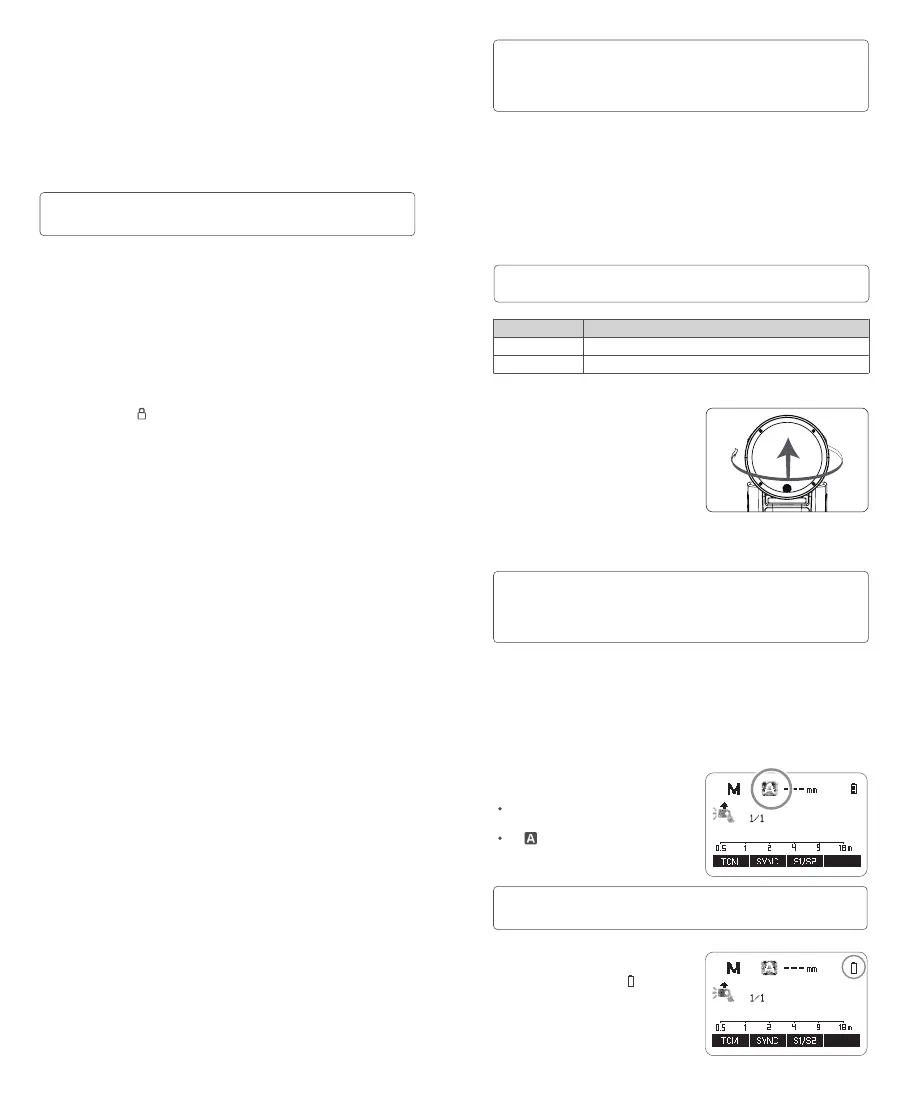
Position
Center
Periphery
Effective Range
0.6~10m / 2.0~32.8 feet
0.6~5m / 2.0~16.4 feet
By pointing the flash head toward a
wall or ceiling, the flash will bounce
off the surface before illuminating
the subject. This can soften shadows
behind the subject for a more
natural-looking shot. This is called
bounce flash.
To set the bounce direction, hold the
flash head and turn it to a satisfying
angle.
Bounce Flash
1. If the wall or ceiling is too far away, the bounced flash might be too weak and
result in underexposure.
2. The wall or ceiling should be a plain, white color for high reflectance. If the bounce
surface is not white, a color cast may appear in the picture.
Note
:
Low Battery Warning
If the battery power is low, < > will
appear and blink on the LCD panel.
Please replace the battery immediately.
ZOOM: Setting the Flash Coverage
The flash coverage can be set automatically or manually. It can be set to
match the lens focal length from 28mm to 105mm. In auto zoom mode,
the focal length changes in response to the camera's zoom lens to provide
optimal flash results.
In manual zoom mode, press the
<ZOOM> button.
Turn the select dial to change the
ash coverage.
If <
> is displayed, the ash
coverage will be set automatically.
If you set the flash coverage manually, make sure it covers the lens focal length so
that the picture will not have a dark periphery.
Note
: