40 41
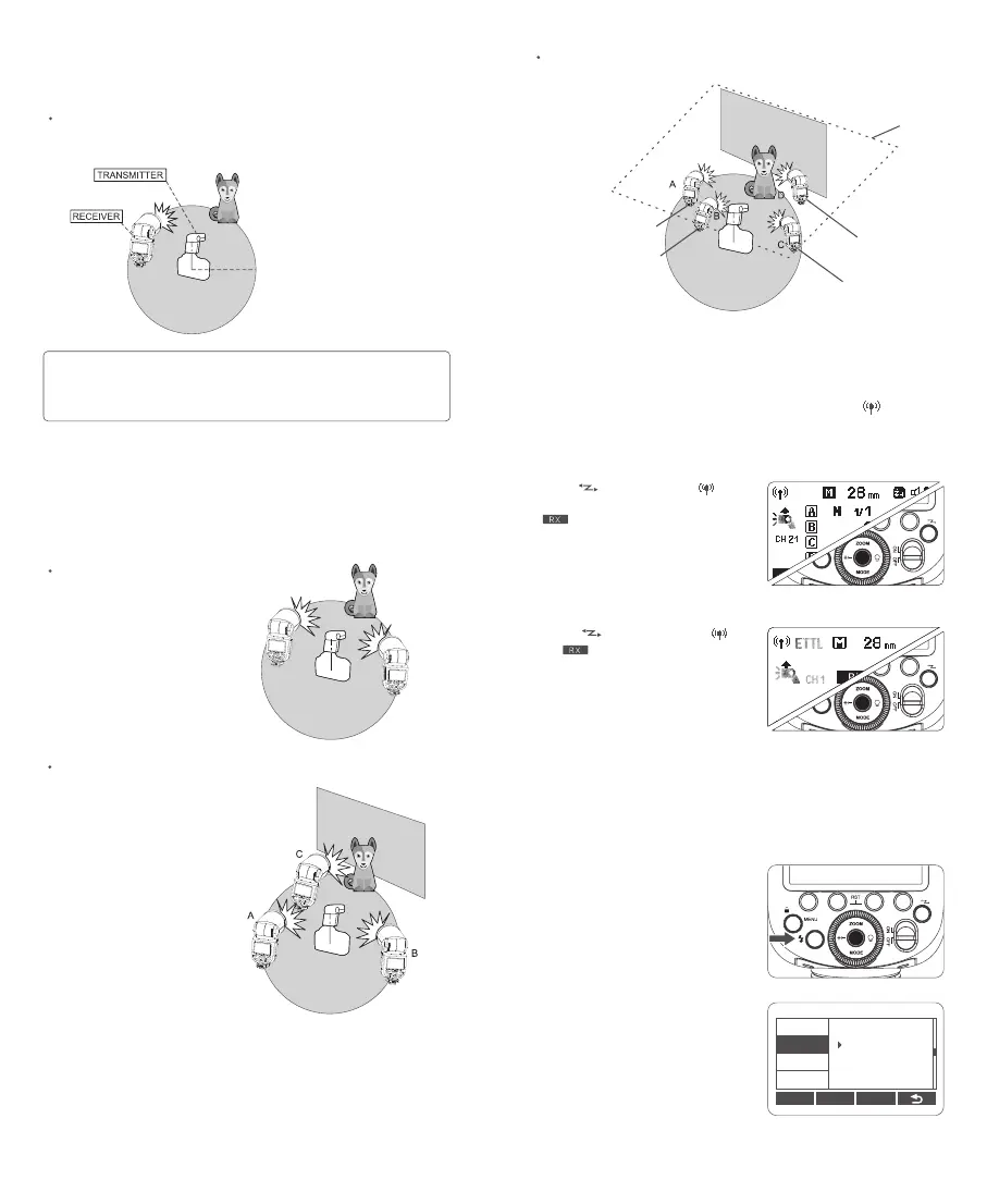
Positioning and Operation Range (Example of wireless flash
shooting)
Auto Flash Shooting with One Receiver Unit
Transmission distance is about 100m
1. Before shooting, perform a test flash and test shooting.
2. The transmission distance might be shorter depending on the conditions such as
positioning of receiver units, the surrounding environment and whether conditions.
Note:
Auto Flash Shooting with Multiple Receiver Groups
You can divide the receiver units into two or three groups and perform E-TTL
II auto flash while changing the flash ratio (flash output ratio). In addition, you
can set and shoot with a different flash mode for each ring group, for up to 4
groups.
Auto Flash Shooting with Two Receiver Groups
Auto Flash Shooting with Three Receiver Groups
Shooting with a Different Flash Mode Set for Each Group
Wireless Settings
Setting the Flash as A Transmitter Unit
Setting the Flash as A Receiver Unit
You can switch between normal flash and wireless flash. For normal flash
shooting, be sure to set the wireless setting to “OFF”, and the <
> won’t be
displayed on the LCD panel.
Press <
> button so that < > is
displayed on the LCD panel, but the
<
> won’t be displayed.
Press <
> button so that < >
and<
> are displayed on the LCD
panel.
Wireless Channel Settings
If there are other wireless flash systems nearby, you can change the wireless
channels to prevent signal interference. The wireless channels of the
transmitter unit and the receiver unit(s) must be set to the same.
1. Press <MENU> menu button to
enter menu setting. Turn the select
dial to <CH>, then press the set
button to choose CH.
2. Turn the select dial to adjust
wireless channel from 01 to 32. Press
the set button to conrm.
C.Fn Ver 0.2
CLEAR
CH
ID
BEEP
STBY
07
SCAN
Ceiling
External Auto
Flash Meter
E-TTL II
Manual Flash
Manual Flash