Do you have a question about the Goodwe EM Series and is the answer not in the manual?
Explains the general behavior and operating modes of the EM system.
Provides explanations of symbols and general safety warnings for the inverter.
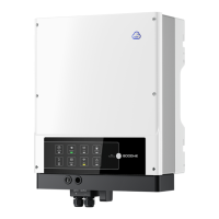
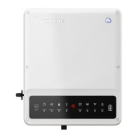
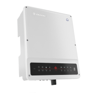
Details the hybrid LED indicators and physical components of the inverter.
Lists common installation errors that can damage the system or inverter.
Lists components to check for upon receiving the hybrid inverter.
Provides rules for selecting a mounting location and specific mounting steps.
Details PV, battery, and AC wiring connections, including specific procedures.
Explains connection details for DRED and remote shutdown devices.
Describes the earth fault alarm connection and its indicator LED.
Information on accessing the SEMS Portal for online monitoring.
Illustrates the overall wiring scheme for EM series hybrid inverters.
Guides users through configuring Wi-Fi connection via web interface or app.
Details the PV Master app for external monitoring and configuration.
Mentions the CEI Auto-Test function for meeting Italian requirements.
Lists error messages, their explanations, reasons, and solutions.
Provides checks and solutions for common problems during operation.
Outlines conditions under which the manufacturer may not provide after-sales services.
Lists detailed technical specifications for different EM series models.
Mentions specific tests like THDi, Zref, RA, XA, RN, XN for Australian requirements.
Provides a checklist to avoid dangers during installation and setup.
The GoodWe EM series of hybrid/bidirectional solar inverters are designed for solar systems that integrate a photovoltaic (PV) system, batteries, loads, and the local grid for comprehensive energy management. The primary function is to optimize system self-consumption, using excess PV power for battery charging and exporting any remaining surplus to the grid. When PV power is insufficient, the battery discharges to support loads. If both PV and battery power are inadequate, the system draws power from the grid.
The EM system typically operates in various modes depending on its configuration. In Mode I, PV energy prioritizes self-consumption, with excess energy charging the battery and any further surplus exported to the grid. Mode II activates when no PV power is available and the battery charge is insufficient, in which case the EM system supplies loads using grid power. Mode III is the back-up mode, engaged during a grid failure, where loads are supplied by PV or battery power. Mode IV allows the battery to be charged using grid power, with adjustable charge time and power via the PV Master app.
For installation, the inverter must be mounted on a solid surface, suitable for its dimensions and weight, and at an angle not exceeding 15°. The ambient temperature should be below 45°C to prevent power derating. The installation site should be covered and protected from direct sunlight, snow, rain, and lightning. It's crucial to ensure enough space around the inverter for proper ventilation. The inverter should not be installed near flammable or explosive substances or strong electromagnetic equipment.
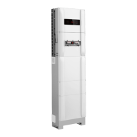
Electrical wiring requires careful attention. For PV wiring, the total short-circuit current of a PV string must not exceed the inverter's maximum DC current, and the minimum isolation resistance to ground must be above 18.33kΩ. PV strings must not be connected to an earth/grounding conductor. Correct PV plugs (MC4, QC4.10, or Amphenol) must be used, and PV cables should be tightly crimped. Battery wiring requires an external DC breaker (≥63A) connected to the batteries, and the battery's nominal voltage must meet EM series specifications. The capacity of a lithium battery pack must be 50Ah or larger, with specific cabling requirements for conductor core section (20-35 mm²). For on-grid and back-up connections, an external AC breaker is necessary, and specific cable dimensions are provided for both on-grid (8-10 mm² conductor core) and back-up (4-6 mm² conductor core) connections. The neutral cable should be blue, line cables black or brown, and the protective earth cable yellow-green, with the PE cable being longer to ensure it remains connected under strain.
The Smart Meter with integral current transformers (CTs) is compulsory for EM system installation, detecting grid voltage, current direction, and magnitude, and communicating via RS485. It's essential that the Smart Meter and CT are correctly configured and connected between the house loads and the grid, matching the CT's direction markings. For three-phase grids, three CTs must be used and connected on the same phase as the Smart Meter power cable.
The inverter includes a Demand Response Enabling Device (DRED) interface for compliance with Australian and New Zealand safety requirements, allowing for remote shutdown. The DRED cable connects to a 6-pin terminal on the inverter. The EM series inverter complies with IEC 62109-2 13.9 for earth fault alarms, indicated by an LED on the inverter cover and email notifications.
The EM series hybrid inverter offers adjustable settings via a special firmware interface, allowing users to configure trip points, trip time, reconnection time, and QU/PU curve values. For split grid systems, specific application instructions are available. The back-up outputs have overload functionality, with the inverter derating for self-protection at high ambient temperatures. The back-up switching time is typically less than 10ms, but external factors can cause system failure in back-up mode, so users are advised to avoid connecting loads dependent on stable energy supply or exceeding maximum back-up capacity. High start-up current surge loads should also be avoided.
For operation and monitoring, the Wi-Fi configuration is essential for online monitoring and maintenance. This can be done via a web interface or the PV Master app. The Wi-Fi module can be reset or reloaded to restore default factory settings if connection issues arise. The PV Master app, available for Android and iOS, allows users to edit system configurations, monitor performance, and configure Wi-Fi. It also includes a CEI auto-test function for Italian requirements.
Maintenance features include ensuring the inverter is fully isolated from all DC and AC power for at least 5 minutes before any work. The heat sink should be cleaned annually with a towel. AC and DC wiring connections should be tightened annually with a torque wrench. The DC breaker should be checked regularly and activated 10 times in a row once a year to clean contacts and extend its lifespan. The waterproof plate of the RS485 connector and other parts should be replaced annually. To ensure IP65 rating compliance, the inverter must be well sealed, and all unused terminals/holes must be sealed to prevent water or dust ingress.
| Type | Hybrid Inverter |
|---|---|
| Battery Voltage Range | 40V to 60V |
| Max PV Input Voltage | 500V |
| Number of MPPTs | 2 |
| Protection Rating | IP65 |
| Communication | WiFi, RS485, USB |
| Rated Power Output | 3000W, 3600W, 4200W, 5000W |
| Max Charging Power | 3kW |
| Max Discharging Power | 3kW |
| Nominal AC Output Power | 3kW to 6kW |
| Max PV Input Power | 4500W, 5400W, 6300W, 7500W |
| Max AC Output Power | 3kW to 6kW |
| AC Output Voltage | 230V |
| AC Output Frequency | 50/60Hz |
| Operating Temperature | -25~60 °C |
| Cooling Method | Natural Cooling |
| Model | EM Series |