Safety Warning
Installation and maintenance of the inverter must be performed by qualified electricians, in
compliance with local authority and grid company standards, wiring rules and requirements (e.g.,
AS 4777 and AS/NZS 3000 in Australia).
Before installing any wiring connection or electrically operating the inverter, all battery and
AC power sources must be disconnected from inverter for at least 5 minutes to ensure the
inverter is totally isolated to avoid electric shock.
The inverter's surface temperature may exceed 60℃ during operation, so please ensure it
has cooled down before touching it, and ensure the inverter is out of reach of children.
Opening the inverter's cover or modifying any components without the manufacturer's
authorization will invalidate the product's warranty.
The inverter must be operated in accordance with the instructions in this user manual;
failure to do so may result in damage to the product, and will invalidate the manufacturer's
warranty.
Appropriate methods must be adopted to protect the inverter from static damage. Any
damage caused by static is not covered by the manufacturer's warranty.
PV negative (PV-) and battery negative (BAT-) connections on the side of the inverter are not
grounded by design. Connecting PV- to earth is strictly forbidden.
PV modules used with the inverter must have an IEC61730 class A rating, and the total
open-circuit voltage of the PV string/array must be lower than the maximum rated DC input
voltage of the inverter. Any damage caused by PV over-voltage is not covered by the manu-
facturer's warranty.
The inverter's built-in residual-current monitoring unit (RCMU) removes DC residual current
above 6mA, so an external RCD (type A) can be used with the system (≥30mA).
In Australia, the inverter's internal switching does not maintain neutral integrity. This must
be addressed with an appropriate external connection configuration, such as that provided
in the system connection diagram for Australia on page 20.
In Australia, the output from the back-up side in the switchbox should be labelled "Main
Switch UPS Supply". The output from the normal load side in the switch box should be
labelled "Main Switch Inverter Supply".
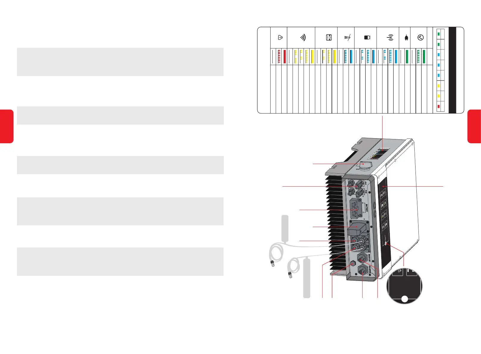
1.3 Product Overview
HYBRID LED INDICATORS
INDICATOR
ENERGY
ON = SYSTEM IS READY
BLINK = SYSTEM IS STARTING UP
OFF = SYSTEM IS NOT OPERATING
ON = BACK-UP IS READY / POWER AVAILABLE
OFF = BACK-UP IS OFF / ON POWER AVAILABLE
ON = BMS AND METER COMMUNICATION OK
OFF = BMS AND METER COMMUNICATION FAILURE
ON = BATTERY IS CHARGING
BLINK 1 = BATTERY IS DISCHARGING
BLINK 2 = BATTERY IS LOW / SOC IS LOW
OFF = BATTERY IS DISCONNECTED / NOT ACTIVE
ON = BATTERY IS ACTIVE AND CONNECTED
BLINK = GRID IS ACTIVE BUT NOT CONNECTED
OFF = GRID IS NOT ACTIVE
ON =
CONSUMING ENERGY FROM GRID / BUYING
BLINK 1 = SUPPLYING ENERGY TO GRID / ZEROING
BLINK 2 = SUPPLYING ENERGY TO GRID / SELLING
ON = Wi-Fi CONNECTED / ACTIVE
BLINK 1 = Wi-Fi SYSTEM RESETTING
BLINK 2 = Wi-Fi NOT CONNECT TO ROUTER
BLINK 4 = Wi-Fi SERVER PROBLEM
OFF = Wi-Fi NOT ACTIVE
ON = FAULT HAS OCCURRED
OFF = NO FAULT
EXPLANATION
SYSTEM BACK-UP COM BATTERY GRID ENERGY Wi-Fi FAULT
BLINK 1 = OVERLOAD OF BACK-UP
OUTPUT / REDUCE LOAD
BLINK 1 = METER COMMUNICATION OK,
BMS COMMUNICATION FAILURE
BLINK 2 = BMS COMMUNICATION OK, METER
COMMUNICATION FAILURE
STATUS
OFF = GRID NOT CONNECTED OR SYSTEM
NOT OPERATING
SYSTEM
GRID
Wi-Fi
COM
FAULT
BATTERY
2 0 1 9
BACK-UP
BMS Communication Cable
DRED
Wi-Fi Box
Battery Terminals
PV Terminals
DC Switch
(Optional)
Wi-Fi Reset/Reload Button
Back-Up Port
On-Grid Port
Exhaust Valve
Reserved RS485
LED Label
BETTERY
Wi-Fi
Reset / Reload
COMBACK-UPSYSTEM
FA U LTWi-FiENERGYGRID
Smart Meter
Communication Cable
To Battery
To Smart Meter
< For reference only
04
03