Accepted Loads:
The EM series inverter is able to supply a continuous 2300VA output or max 3500VA in less than 10
seconds on the back-up side to support back-up loads. The inverter will derate for self-protection
at high ambient temperatures.
• Acceptable back-up loads: Television, computer, fridge, fan, illumination lamps, microwave oven,
electrical rice cooker and router etc.
• Unacceptable back-up loads: Air conditioner, water pump, heaters, washing machine, electro-
magnetic oven, compression engine, hair drier and vacuum cleaner etc. Any other loads with
high inrush current at start-up are also unacceptable.
Note:
For convenient maintenance, please install a SP3T switch on the back-up side and the on-grid
side. This enables adjustment of supply loads with back-up, grid or default settings.
1. The back-up load is supplied by the
back-up side.
2. The back-up load is isolated.
3. The back-up load is supplied from the grid
side.
Back-Up
SP3T
1
2
3
On-Grid
GridLoad
Declaration for Back-Up Overload Protection
The inverter will restart if overload protection is triggered. Preparation time for restarting will
increase in duration (one hour at most) if overload protection is triggered repeatedly. Take the
following steps to restart the inverter immediately:
Decrease back-up load power to within maximum limits.
In the PV Master app → Advanced Setting → Click "Reset Back-Up Overload History".
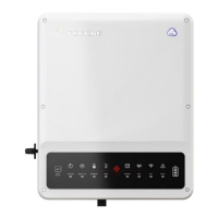
Wi-Fi
Reset/Reload
SYSTEM
GRID
BACK-UP
2019
ENERGY
COM
Wi-Fi
BATTERY
FAULT
Note:
1. Please use the Smart Meter with 3 CTs supplied with the product.
2. The CT cable is 3m as default, but can be extended to a maximum of 5m.
3. The Smart Meter communication cable (RJ45) is attached to the inverter ("To Smart Meter"
cable). It can be extended to a maximum of 100m, and must use a standard RJ45 cable and
plug, as below:
2.4.4 Smart Meter & CT Connection
Make sure the AC cable is fully isolated from AC power before connecting the Smart
Meter & CT.
The Smart Meter with integral current transformer (CT) included with the product is compulsory
for EM system installation. It is used to detect grid voltage, current direction and magnitude. It also
communicates with the inverted RS485 communication.
Note:
1. The Smart Meter & CT is correctly configured. Please do not alter any settings on the Smart
Meter.
2. Only one Smart Meter can be used for each EM series inverter.
3. Three CTs must be used for one Smart Meter, and must be connected on the same phase with
Smart Meter power cable.
POWER
ENERGY
COM
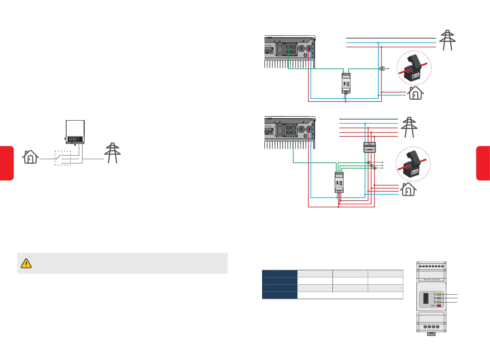
Smart Meter LED Indications
STATUS
POWER
ENERGY
COM
OFF
Not working
/
ON
Working
Importing
Blink once when transferring data to the inverter
Blinking
/
Exporting
BACK-UP ON-GRID
BMS
RS485
DRED
CAN
BACK-UP ON-GRID
BMS
RS485
DRED
CAN
Smart Meter & CT Connection Diagram
• For single phase grid
PE
N
L3
L2
L1
Grid
Load
CT A connect to L1
CT B connect to L2
CT C connect to L3
CT C
CT B
CT A
To Smart Meter
Power Meter
Grid side
Smart Meter
• For three phase grid
PE
N
L
Grid
Load
CT
To Smart Meter
Grid side
Smart Meter
16
15
 Loading...