Detailed Pinout for Each Port on the Inverter
BMS: CAN communication is configured by default. If RS485 communication is to be used, please
contact after-sales support to obtain the correct communication cable.
Position
1
2
3
4
5
6
7
8
Colour
Orange-white
Orange
Green-white
Blue
Blue-white
Green
Brown-white
Brown
EMS
485_A
485_B
485_A
NC
NC
485_B
NC
NC
BMS Function
485_A2
NC
485_B2
CAN_H
CAN_L
NC
NC
NC
Smart Meter Function
NC
NC
485_B1
NC
NC
485_A1
485_B1
485_A1
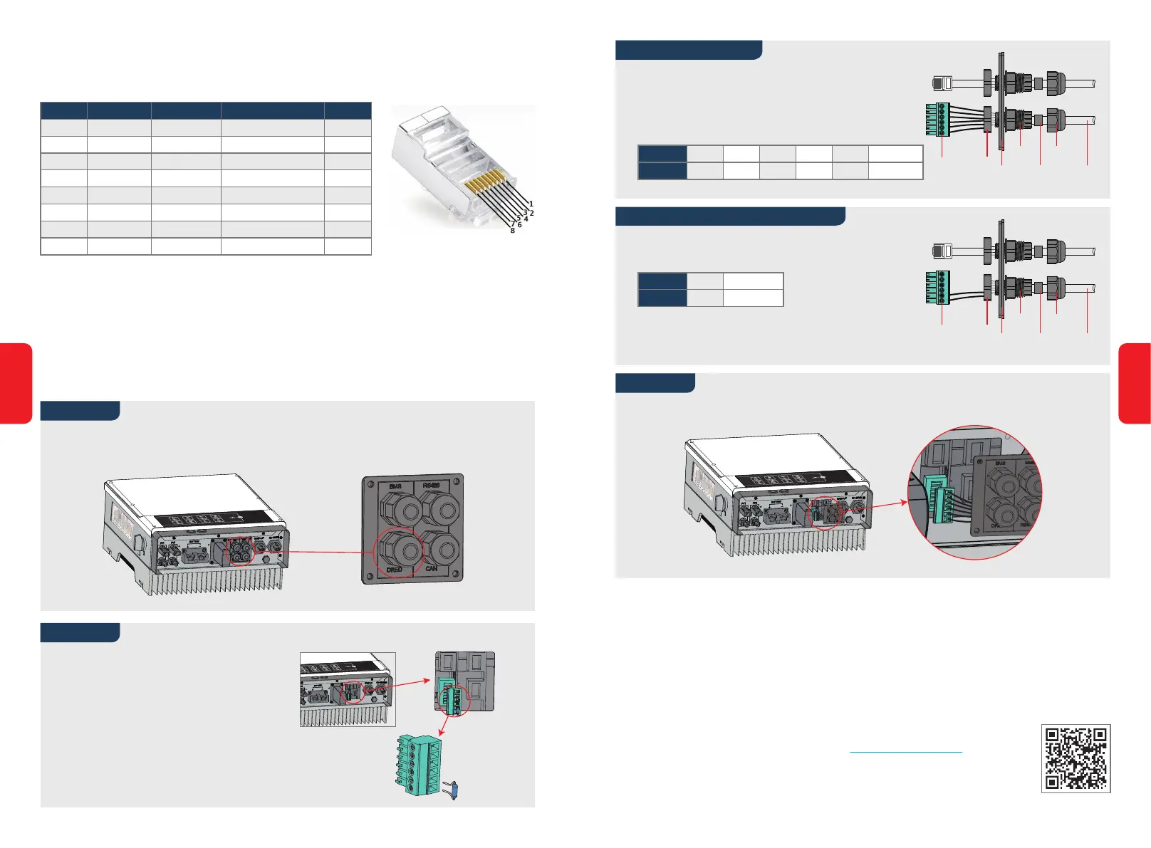
2.5 DRED and Remote Shutdown Device Connection
A DRED (demand response enabling device) is required for installation in Australia and New
Zealand (and can also be used for remote shutdown in European countries), in compliance with
Australia and New Zealand safety requirements (or those of European countries). The inverter
includes the required control logic and DRED interface, but the DRED itself is not provided by the
inverter manufacturer.
Connection details for DRED and remote shutdown are shown below:
NO.
Function
1
DRM1/5
2
DRM2/6
3
DRM3/7
4
DRM4/8
5
REFGEN
6
COM / DRMO
Step 4
Step 3-1 For DRED
1. Push the cable through the plate.
2. Wiring for connector positions 5 and 6, respectively.
Connect the DRED terminal at the correct location on the inverter.
Step 3-2 For Remote Shutdown
1. Push the DRED cable through the plate.
2. Connect the DRED cable to the 6-pin terminal.
The function of each position on the connector
is shown below.
123456
Screw Nut
The
Insulator
Screw Cap
RS485
Communication Board
CableSingle Hole
Seal Ring
123456
Screw Nut
The
Insulator
Screw Cap
RS485
Communication Board
CableSingle Hole
Seal Ring
NO.
Function
5
REFGEN
6
COM / DRMO
Unscrew the plate from the inverter.
Note: DRED should be connected via the "DRED Port" as the figure shows.
Step 1
Step 2
1. Unplug the 6-pin terminal and disconnect
the resistor.
2. Remove the resistor and retain the 6-pin
terminal for the next step.
Note: The 6-pin terminal in the inverter has
the same pinout as the DRED. Please
leave it in the inverter if no external
device is connected.
2.6 Earth Fault Alarm Connection
The EM series inverter complies with IEC 62109-2 13.9. The fault indicator LED on the inverter
cover will light up and the system will email fault information to customer.
The inverter should be installed at eye level for convenient maintenance.
2.7 SEMS Portal
SEMS Portal is an online monitoring system. After installation of the communica-
tion connection is complete, you can access www.semsportal.com or download
the app by scanning the QR code to monitor your PV plant and device.
Please contact the after-sales team for more information on how to use SEMS
Portal.
SEMS Portal App
18
17

 Loading...