06 Electrical Connection
User Manual V1.3-2023-01-31
24
WARNING
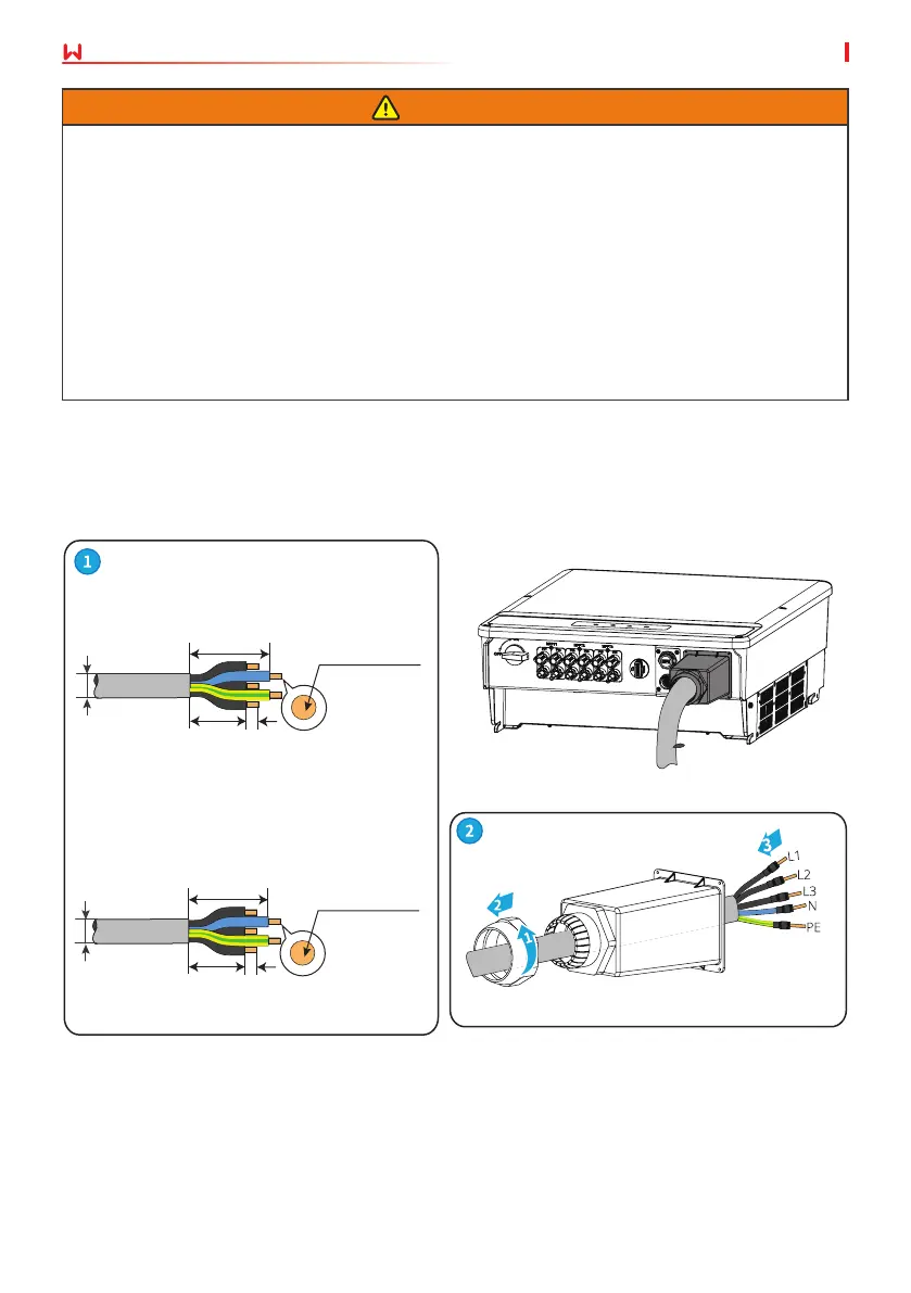
• Pay attention to the silkscreens L1, L2, L3, N, PE on the AC terminal. Connect the AC cables
to the corresponding terminals. The inverter may be damaged if the cables are connected
inappropriately.
• Make sure that the whole cable cores are inserted into the AC terminal holes. No part of
the cable core can be exposed.
• Make sure that the cables are connected securely. Otherwise, the terminal may be too hot
to damage the inverter when the inverter is working.
• The AC terminals can be connected in three-phase four-wire or three-phase ve-wire. The
actual wiring method may be dierent. The gure below takes the three-phase ve-wire as
an example.
• Reserve certain length of PE cable. Make ensure that the PE cable is the last one to bear the
stress when the AC output cable is under tension.
Step 1 Prepare the AC output cable.
Step 2 Disassemble the AC cover.
Step 3 Crimp the AC cable OT terminal and route the cable into the AC cover.
Step 4 Fasten the AC output cable and secure the AC cover.
10mm
2
≤S≤25mm
2
90mm
70mm 11mm
Φ
22~30mm
GW12KLV-MT, GW15KLV-MT, GW20KLV-
MT, GW25K-MT, GW29.9K-MT, GW30K-
MT, GW36K-MT:
GW30KLS-MT, GW35KLS-MT, GW50KS-MT,
GW60KS-MT, GW50KS-MT-EU and GW60KS-
MT-EU:
Φ
30~40mm
70mm 15mm
100mm
35mm
2
≤S≤50mm
2
 Loading...