Installation
3A6931A 17
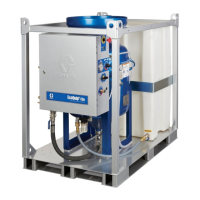
2. Using the mounting bracket (209), attach the ram
junction box (208) to the ram using two screws (214)
and washers (213) as shown in Figure 22 on page
16.
3. Attach the mounting brackets (210, 211) with four
screws (215), nuts (216), and washers (213).
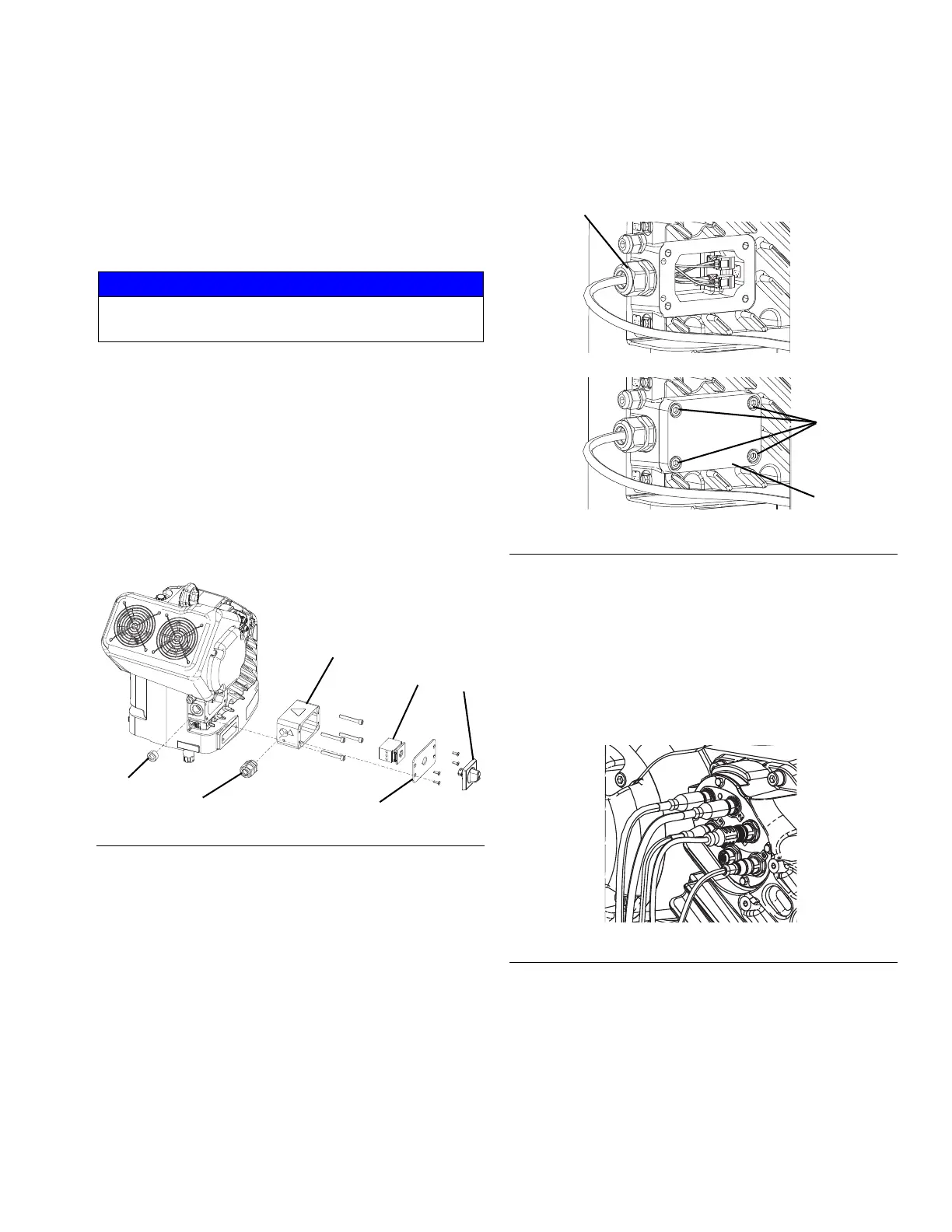
4. Disconnect the wires from the disconnect block (A).
5. Remove and discard the driver junction box cover
(C) and the disconnect switch (B) from the driver.
See Figure 23.
6. Remove and discard the extrusion (D), then remove
and discard the plug (E).
7. Remove the cord grip and save it for reuse.
8. Install the electric driver (201) using the same
hardware that was used with the air motor.
9. Install the cord grip that was removed in step 7 into
the driver junction box where the plug was removed.
See Figure 24.
10. The power cable from the ram junction box (208) is
routed through the cable track. Run it through the
cord grip and connect it using the supplied
connectors. Connect the ground wire to one of the
two green ground terminals inside the driver
junction box.
11. Install the new driver junction box cover using the
four screws. The cover and screws are included with
the cable track assembly.
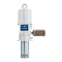
12. Connect the cable track connections as shown in
Figure 25.
a. Connect the two CAN connectors to ports 1 and
2.
b. Connect the 5 pin connector to port 3.
c. Connect the 8 pin connector to port 4.
NOTE: Use Figure 3 on page 10 for further reference.
13. Use the shaft adapter included in the kit and
connect the electric driver to the pump coupling,
pump lower, and tie rods that were removed from
the air motor pump. Refer to the E-Flo SP Supply
Systems Installation-Parts manual. See Related
Manuals on page 2.
NOTICE
Do not over-torque the ram junction box mounting
brackets. Over-torquing can damage the cylinder.
FIG. 23: Remove Driver Junction Box
FIG. 24: D200 Driver Junction Box Cover
FIG. 25: D200 Cable Track Connections