Installation
3A6931A 27
3. Mount the transformer onto the ram cylinder so the
conduit (707 or 811 depending on the kit) containing
the conductors from the transformer can reach the
ram junction box as shown in Figure 55.
a. For kit 25E203, use the eight screws (704),
washers (705), and nuts (703) included in the kit
to attach the transformer’s mounting bracket to
the cylinder.
b. For kit 25E202, use the two U-bolts (805), four
washers (807), and four nuts (804) included in
the kit to attach the transformer’s mounting
bracket to the cylinder.
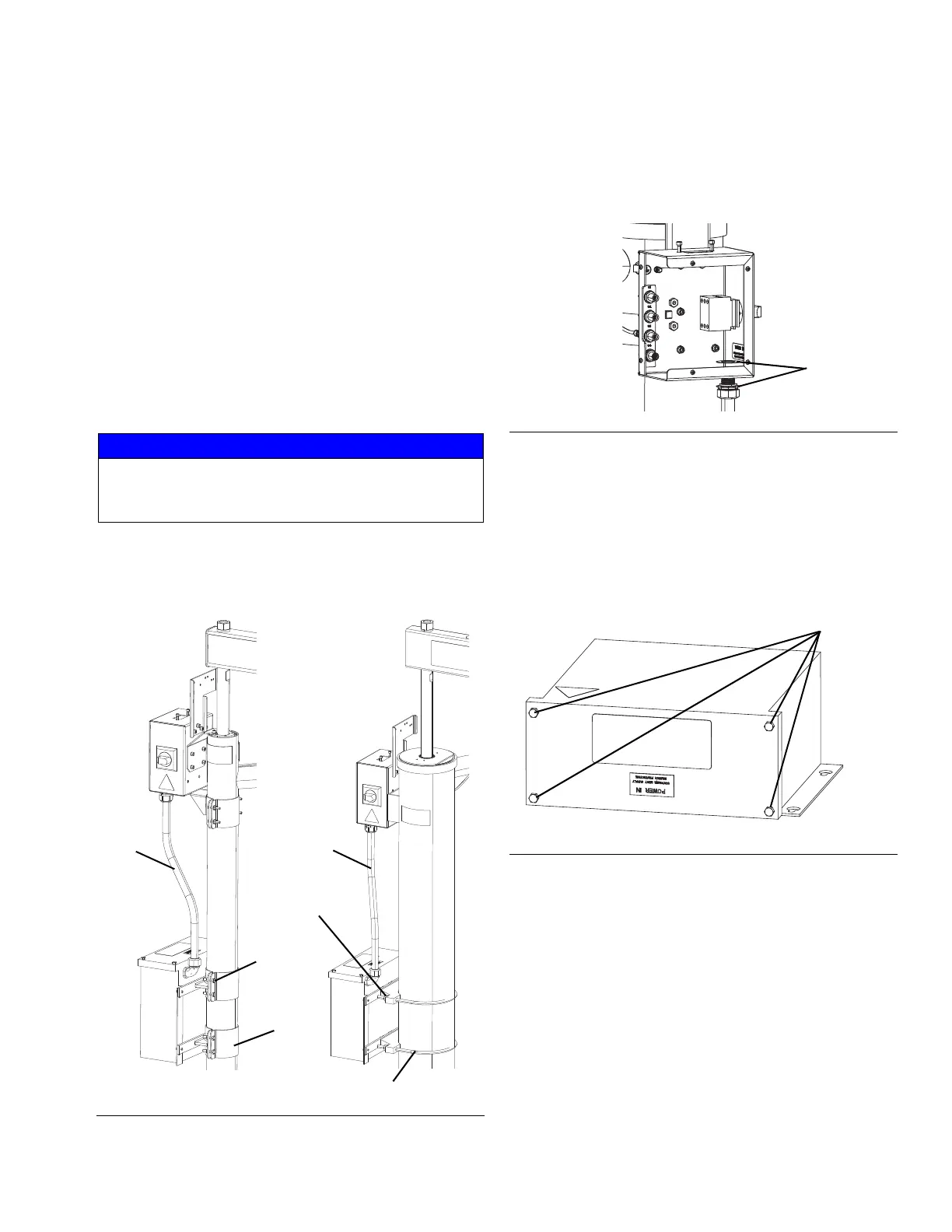
4. Run the conduit and install the cord grip into the
hole in the bottom of the ram junction box.
5. Use the two flat washers (719 or 821 depending on
the kit) when attaching the cord grip. One washer
should be on the outside of the ram junction box and
the other on the inside. See Figure 56.
Connect the Ram Transformer Power
1. Follow the steps in Connect Power to an Electric
Ram System on page 23 before connecting power
to the transformer.
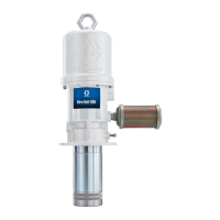
2. Remove the four screws on the transformer as
shown in Figure 57 and remove the front cover.
NOTICE
Do not over-torque the screws when mounting the
transformer to the ram. Over-torquing can damage
the cylinder.
FIG. 55: Ram Transformer Installation
Kit 25E203
Kit 25E202
703
704
705
701
707
811
805
804
807
FIG. 56: Conduit and Cord Grip Installation
FIG. 57: Ram Transformer