Pump Operation
332291P 27
Pump Operation
The G3 Pump can be controlled using an external, user
supplied, power source and controller.
Refer to System Configuration and Wiring, page 13
for required fusing and wiring information.
NOTE:
• When using an external power source and control-
ler, Pump ON (Run) Time should be set for no lon-
ger than 30 minutes.
• In most cases, Pump OFF (Rest) Time should be
twice as long as Pump ON (Run) time. If alternative
ON / OFF times are required, contact Graco Cus-
tomer Service for assistance.
Low Level Output Option
Some G3 pumps without controllers include a Low
Level Output Option. It can be configured with an M12
connector in code location “h” or with a DIN connector
in code location “m”. (See Understanding the Model
Number, page 5.) The low level signal is monitored
across PINS 3 and 4. For PIN 3 and 4 locations and wir-
ing information the Low Level Outputs diagram, page
16.
NOTE: A low level warning is triggered when the con-
troller detects PINS 3 and 4 have momentarily closed.
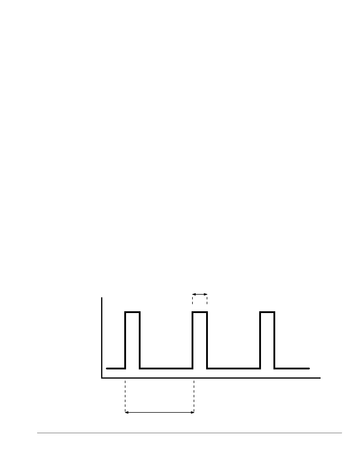
Grease Pumps
When the grease level has reached a low warning level,
PINS 3 and 4 momentarily close (1 time per paddle rev-
olution) sending the signal that the fluid has reached a
low level to the controller.
To ensure that a low level condition has been met, 3 or
more low level triggers must be detected within 1 min-
ute or less.
See F
IG. 29 for an illustration of a typical Low Level Out-
put response to low grease level.
Typical Low Level Output Response with Low Level Fluid in Grease Models
FIG. 29