Installation
332291P 9
Installation
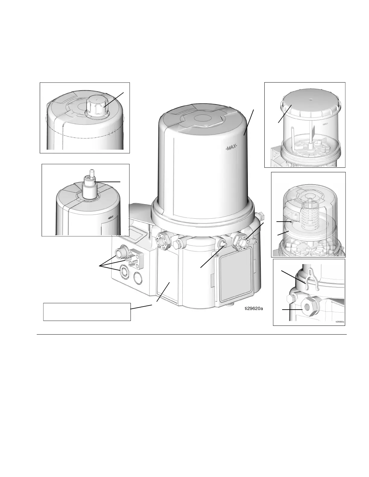
Component Identification
Key:
A Reservoir
B Adjustable Pump Element (1 included. Can
accommodate 3 total)
C Pressure Relief Valve (Not included (not shown) / required
for each outlet - Available from Graco. See Parts, page
35.)
D Zerk Inlet Fill Fitting (1 included / grease models only)
E Pump Outlet Plug (2 included)
F Volume Control Spacers (2 included. More spacers = less
output volume per stroke) (also see F
IG. 18, page 20)
G Fuse (DC models only - Not included, not shown.
Available from Graco. See Parts, page 34.)
H Power / Sensor Panel (both sides; only one side shown)
I Part Number / Model Number example only shown, (see
page 5, Understanding the Model Number, for details)
J Power Cord (Not shown)
K Follower Plate (grease models only / not available on all
grease models)
L Vent Hole for Follower Plate (grease models only / not
available on all grease models)
M Fill cap (oil models only)
N Auto-Fill Shut Off
P Top Fill Lid
FIG. 2
A
D
H
E
I
G3-G-24NC-2L0A00-L0C00000
96GXXX
P
M
Grease Models
Auto-Fill Shut Off Models
N
F
B
K
L
Grease Models with
Follower Plate
Oil Models
Top Fill Models