Setup
332291P 19
Setup
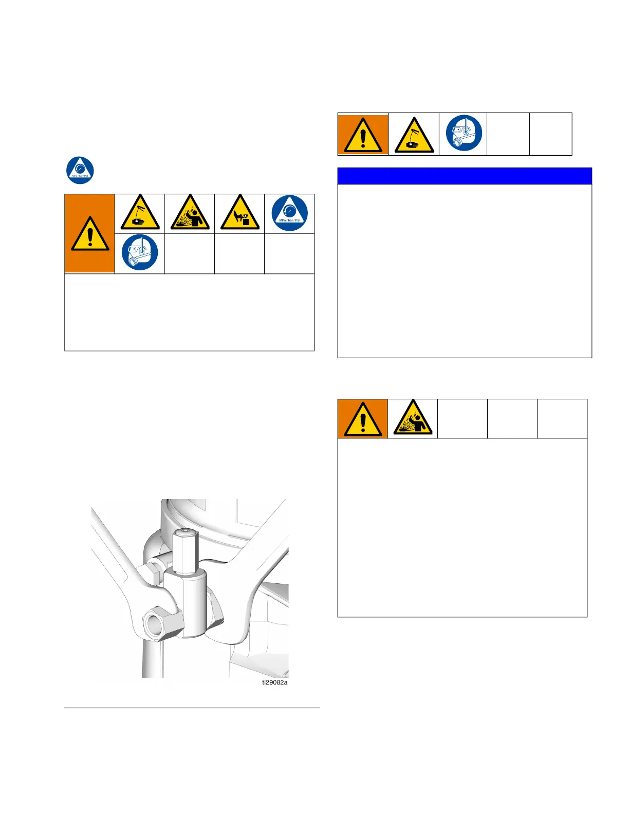
Pressure Relief Procedure
Follow the Pressure Relief Procedure whenever
you see this symbol.
Relieve pressure at the pump element using two
wrenches working in opposite directions on the pump
element and pump element fitting to slowly loosen fit-
ting only until fitting is loose and no more lubricant or air
is leaking from fitting. Repeat for each pump element
installed (F
IG. 17).
NOTE: When loosening pump element fitting, do not
loosen pump element. Loosening pump element will
change the output volume.
Connect to Auxiliary Fightings
Pressure Relief Valves
NOTE: A pressure relief valve can be purchased from
Graco. See Parts, page 35.
This equipment stays pressurized until pressure is
manually relieved. To help prevent serious injury
from pressurized fluid, such as skin injection, splash-
ing fluid and moving parts, follow the Pressure Relief
Procedure when you stop dispensing and before
cleaning, checking, or servicing the equipment.
FIG. 17
NOTICE
Do not attach unsupported equipment to auxiliary fit-
tings such as fill ports and pump element. Attaching
unsupported equipment to these fitting can result in
irreparable housing damage.
• Always use two wrenches working in opposite
directions when connecting anything to pump ele-
ment or auxiliary fittings. See F
IG. 17 for an exam-
ple.
• Torque pump element fittings to 50 in. lbs (5.6
N•m).
• When connecting pump element into housing
torque to 50 in. lbs (5.6 N•m).
To prevent over-pressurization, which can result in
equipment rupture and serious injury, a pressure
relief valve appropriate for the lubrication system
must be installed close to every pump outlet to alle-
viate unintended pressure rises in the system and
protect the G3 pump from damage.
• Only use a pressure relief valve that is rated for
no more than the working pressure of any com-
ponent installed in the system. See Technical
Data, page 33.
• Install a pressure relief valve close to every
pump outlet; before any auxiliary fitting.