Installation
14 312394C
Level Sensors
Polyethylene Tanks
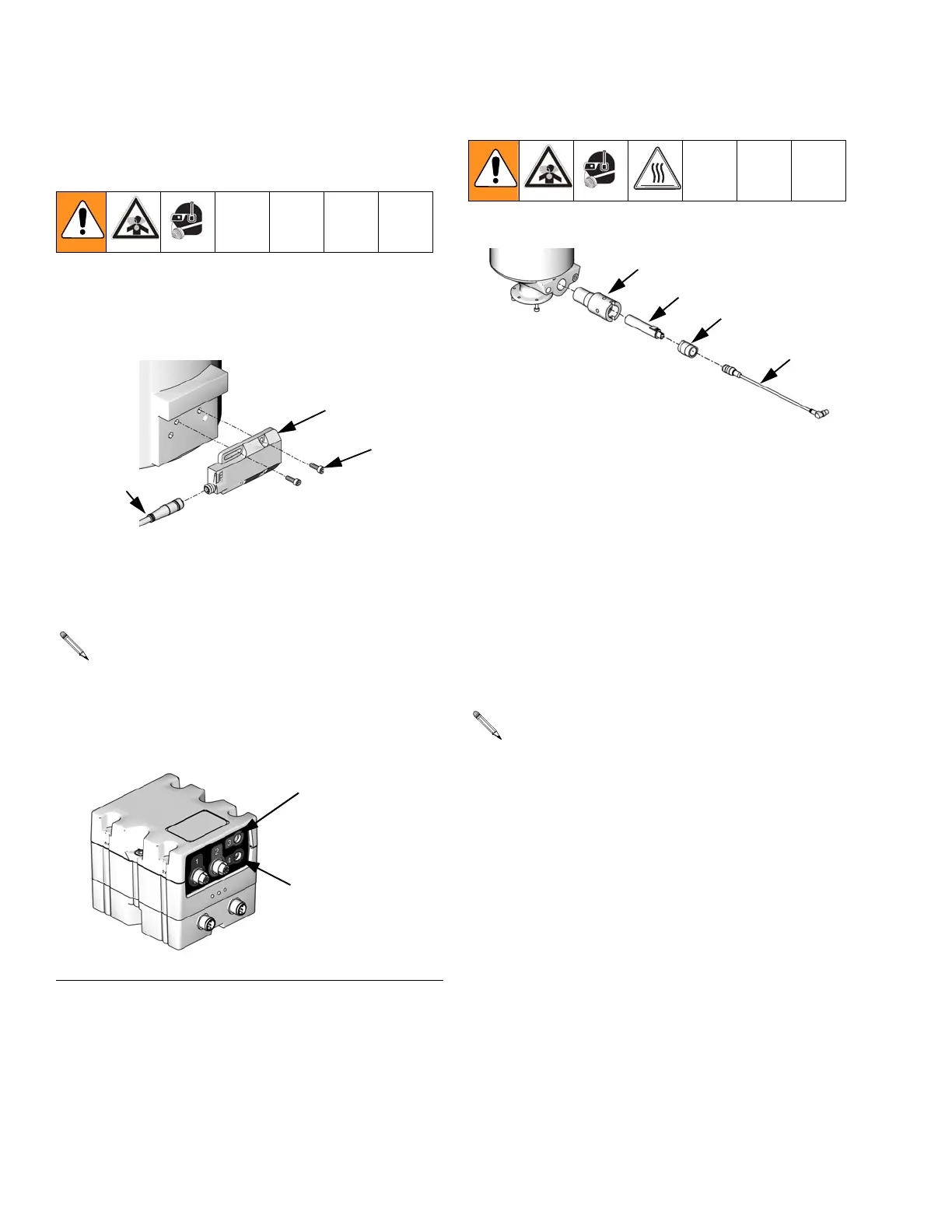
1. Install sensor (2001) using two screws (2003). The
cable (2002) for the sensor should be pointing
towards the center of the machine base.
2. Plug the sensor cable (2002) into the connector on
the Fluid Control Module as shown in F
IG. 1.
3. Calibrate the sensors. See Level Sensor Calibra-
tion, page 17.
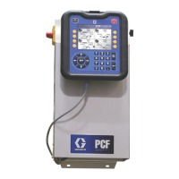
Stainless Steel Tanks
1. Empty the tank.
2. Insert the PTFE proximity sensor well (2102) into
the tank and turn until flush with the flat face of the
tank.
3. Insert the proximity sensor (2101) into the proximity
sensor well (2102).
4. Hand tighten the well cap (2103) into the proximity
sensor well.
5. Plug the sensor connector (2104) into the connector
on the Fluid Control Module as shown in F
IG. 1.
6. Calibrate the sensor. See Level Sensor Calibra-
tion, page 17.
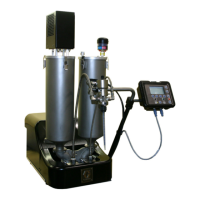
Each machine will have either one or two Fluid
Control Modules, each labeled as #1 or #2. Fluid
Control Module #1 is always used for the low level
sensors. Fluid Control Module #2 is always used for
the high level sensors. See F
IG. 1.
F
IG. 1: Fluid Control Module
2003
2001
2002
ti12493a
High Volume Side
Low Volume Side
ti12337a
Each machine will have either one or two Fluid
Control Modules, each labeled as #1 or #2. Fluid
Control Module #1 is always used for the low level
sensors. Fluid Control Module #2 is always used for
the high level sensors. See F
IG. 1.
2102
2101
2103
2104
ti12494a