Installation
312394C 15
Accumulators
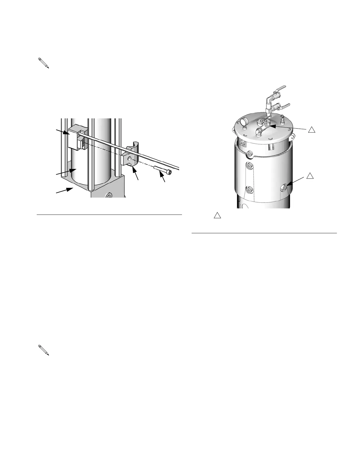
1. Place the main sensor body (144a) against the side
of the main cylinder (123) wall.
2. Line up the bolt holes of the clamp (144b) and the
main sensor body (144a). Lightly clamp the two
together around the nearest tie rod by finger tighten-
ing the socket head cap screw (144c) provided.
3. For accumulator low level sensors, once the
screw (144c) is finger-tight, slide the sensor (144)
so it is located 1/2 in. (13 mm) above the bottom
pump flange (111).
For accumulator high level sensors, once the
screw (144c) is finger-tight, slide the sensor (144)
so it is located 1-1/2 in. (38 mm) below the top pump
flange (111).
4. Plug the sensor connector into the connector on the
Fluid Control Module as shown in F
IG. 1.
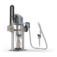
Auto-Refill Installation
The Auto-Refill assembly is shipped uninstalled. The
Auto-Refill assembly can be installed in multiple places
on the tanks. See F
IG. 3.
The accumulator level sensors (144) can be
installed on any side of the main cylinder (123).
However, the sensor must be the specified distance
from the pump flange.
F
IG. 2
Each machine will have either one or two Fluid
Control Modules, each labeled as #1 or #2. Fluid
Control Module #1 is always used for the low level
sensors. Fluid Control Module #2 is always used for
the high level sensors. See F
IG. 1.
ti12592a
144a
144b
144c
111
123
F
IG. 3: Auto-Refill Installation Locations
ti12393a
1
Possible locations for Auto-Refill installation.
1
1