EasyManua.ls Logo

Graco ProMix 2KS User Manual

Graco ProMix 2KS
134 pages
To Next Page IconTo Next Page
Page #1 background imageLoading...
Page #1 background image
312779E
EN
Operation
ProMix
®
2KS
Plural Component Proportioner
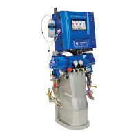
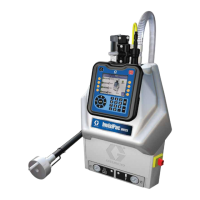
Automatic system for proportional mixing of plural component coatings, with Wall Mount
Fluid Station or RoboMix Fluid Station. For professional use only.
Approved for use in explosive atmospheres (except the EasyKey).
Automatic System with Wall Mount Fluid Station
Automatic System with RoboMix Fluid Station
TI12553a
TI12552a
See pages 4-7 for model information, including maxi-
mum working pressure. Equipment approval labels are
on page 3. Some components shown are not included
with all systems.
Important Safety Instructions
Read all warnings and instructions in this
manual. Save these instructions.
#53
II 2 G0359
Get other manuals https://www.bkmanuals.com
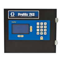
Table of Contents

Other manuals for Graco ProMix 2KS

Questions and Answers:

Graco ProMix 2KS Specifications

General IconGeneral
BrandGraco
ModelProMix 2KS
CategoryIndustrial Equipment
LanguageEnglish

Summary

Operation

ProMix® 2KS

Electronic two-component paint proportioner for mixing plural component coatings.

Plural Component Proportioner

System for proportional mixing of plural component coatings.

Important Safety Instructions

System Configuration and Part Numbers

Wall Mount Fluid Station Configurator Key

Key for configuring part numbers for Wall Mount Fluid Station systems.

RoboMix Fluid Station Configurator Key

Key for configuring part numbers for RoboMix Fluid Station systems.

Warnings

FIRE AND EXPLOSION HAZARD

Warnings related to flammable fumes and preventing fire and explosion.

ELECTRIC SHOCK HAZARD

Warnings related to grounding, setup, and usage to prevent electric shock.

INTRINSIC SAFETY

Warnings regarding the proper installation and connection of intrinsically safe equipment.

SKIN INJECTION HAZARD

Hazards associated with high-pressure fluid injection and necessary precautions.

EQUIPMENT MISUSE HAZARD

Hazards related to improper operation, misuse, or alteration of the equipment.

TOXIC FLUID OR FUMES HAZARD

Hazards from toxic fluids or fumes and necessary safety measures.

PERSONAL PROTECTIVE EQUIPMENT

Requirements for protective equipment to prevent serious injury during operation or servicing.

Overview

Component Identification and Definition

Identification and description of key system components.

EasyKey Display and Keyboard

Run Mode Screens

Status Screen

Detailed explanation of the information presented on the Status Screen.

Manual Override Screen

Screen for manually controlling system operations and modes.

Flow Control Calibration

Procedure for calibrating the flow control system for each recipe.

Alarms Screen

Screen displaying active alarms and their E-Codes.

Level Control Screen

Screen showing current fluid volumes and alarm levels.

Setup Mode

Password Screen

Screen for entering password to access Setup mode.

Set Up Home Screen

Main screen for navigating Setup Mode options.

System Configuration Screens

Screens for configuring system settings and options.

Option Screens

Advanced Setup Screens

Advanced Setup Screen 1

Setup for Flow Control Override, Manual Override, Potlife Volume, and Color/Catalyst Purge/Fill.

Advanced Setup Screen 2

Setup for Purge Sources, Chop Type, and Chop Times.

Advanced Setup Screen 3

Setup for Purge Times, Chop Time, and Mixed Material Fill Time.

Advanced Setup Screen 4

Setup for K-Factor values for meters.

Advanced Setup Screen 5

Setup for Flow Rate Range, Tolerance, Ki, Kp, and Alarm Time.

Advanced Setup Screen 6

Status of recipe analog inputs and digital outputs.

Advanced Setup Screen 7

Status of digital inputs and digital outputs.

Advanced Setup Screen 8

Setup for Special Outputs timing and configuration.

Recipe Setup Screens

Recipe Setup Screen 1

Setup for Ratio, Ratio Tolerance, and Color/Catalyst Valves.

Recipe Setup Screen 2

Setup for Minimum Flush Volume, Potlife Time, and Color/Catalyst Purge/Fill.

Recipe Setup Screen 3

Setup for Purge Sources, Chop Type, and Chop Times for recipes.

Recipe Setup Screen 4

Setup for Purge Times, Chop Time, and Mixed Material Fill Time for recipes.

Recipe Setup Screen 5

Setup for K-Factor values for recipes.

Recipe Setup Screen 6

Setup for Flow Rate Monitor, Low Flow Limit, and High Flow Limit.

Recipe Setup Screen 7

Setup for Special Outputs timing and configuration for recipes.

Calibration Screen

ProMix 2KS Integration Specifics

Discrete I/O vs Network Communications

Overview of system integration methods using Discrete I/O or Network Communications.

Discrete I/O

Requirements and connections for Discrete I/O integration.

Automation Flow Charts

Integrated Flow Control

Flow Control Calibration

Automatic routine to establish a pressure vs flow profile.

Flow Control Troubleshooting

Steps to diagnose and resolve issues with Flow Command not producing fluid output.

System Operation

Typical PLC Interaction with ProMix 2KS

Description of typical interaction between a PLC and the ProMix 2KS.

Start Up

Shutdown

Pressure Relief Procedure

Purging

Solvent Push Feature

Meter Calibration

Color Change

Alarms and Warnings

Alarm Troubleshooting

Schematic Diagrams

System Pneumatic Schematic

Pneumatic schematic illustrating air and fluid flow paths.

System Electrical Schematic

Electrical schematic showing wiring and connections for the system.

EasyKey Electrical Schematic

Electrical schematic specific to the EasyKey unit.

Graco Standard Warranty

Related product manuals