Repair
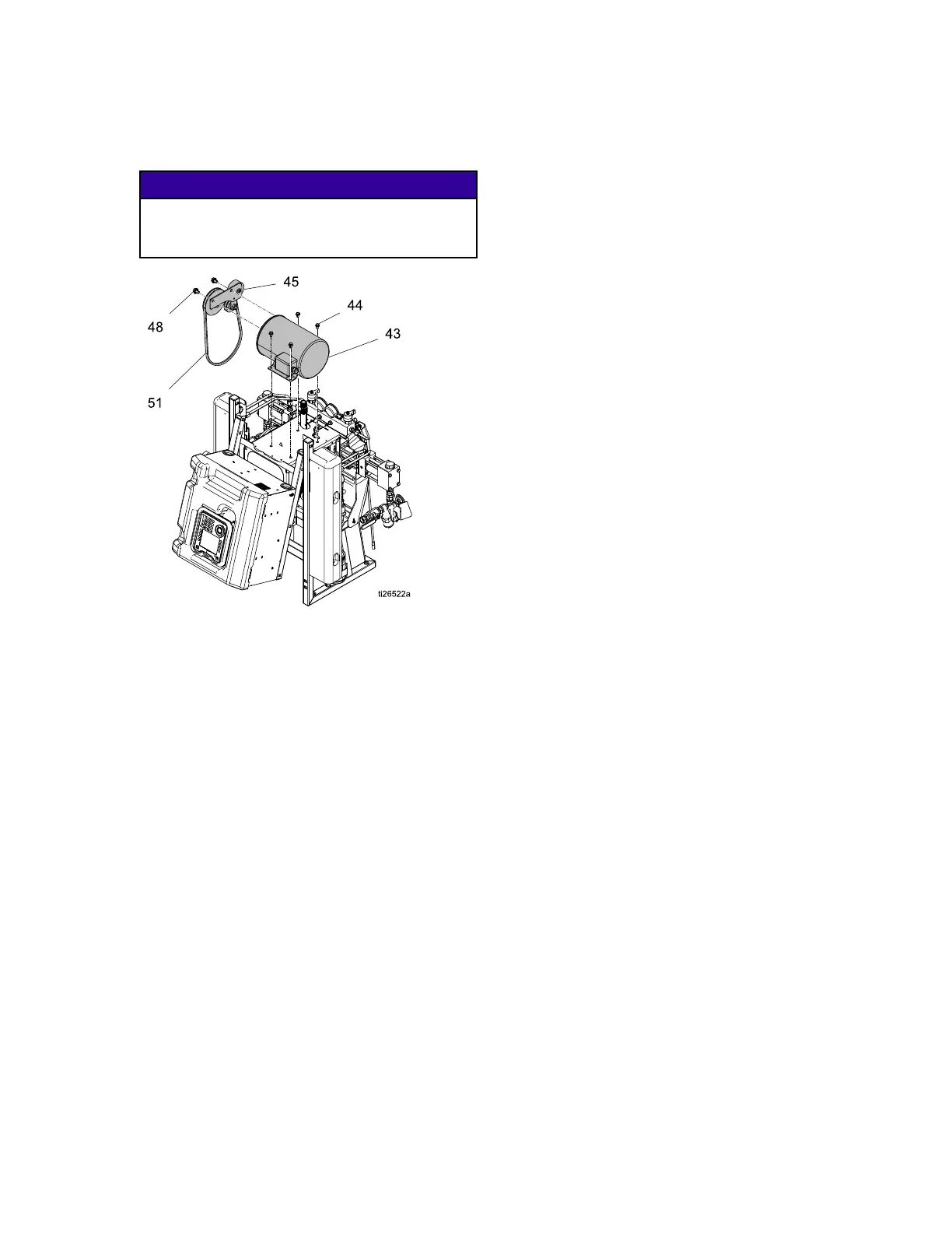
6.Removethebelt(51).SeeReplaceBelt,page58.
Removethetwopulleyscrews(48)andthebelt
tensioningassemblyfromthemotor.
NOTICE NOTICE
NOTICE
Topreventdamagetocables,donotcrush
orstrainanycablesnearthepointwherethe
framehalveshinge.
Figure5MotorandBeltAssembly
7.Removetheelectricmotorjunctionboxcover
(43).
8.Disconnectthemotorcables.See
ElectricalSchematics,page102.
9.Noteorlabelthewireconnections.Seethe
ElectricalSchematics,page102andthediagram
insidethemotorjunctionboxcover.Themotor
mustoperatecounter-clockwisewhenlookingat
theoutputshaft.
10.Removethemotor.
Installation Installation
Installation
1.Placethemotorontheunit.
2.Fastenthemotorwithbolts.
3.Connectthewires,usingwirenuts.See
ElectricalSchematics,page102,andthe
diagraminsidethemotorjunctionbox.
Note
For3–PhaseMotors,themotormust
rotatecounterclockwisewhenviewed
fromtheshaftend.Ifrotationisincorrect,
reversepowerleadsL1andL2.Follow
Connect Connect
Connect
Electrical Electrical
Electrical
Cord Cord
Cord
instructionsin
thesystemoperationmanual.
4.Replacebracket(133)andthebeltandheater
covers(131,132,134).
5.Raiseelectricalenclosureintothevertical
positionandensurewiresarenotpinched
betweentheframehalves.Replaceandtighten
bolts(3).
6.Openelectricalenclosure.ConnecttheAside
heaterconnectortheTCM.
7.Securethesystemtooriginalmountinglocation.
8.Returntoservice.
334946H 57
 Loading...