Troubleshooting
Pumps Do Not Reverse Direction
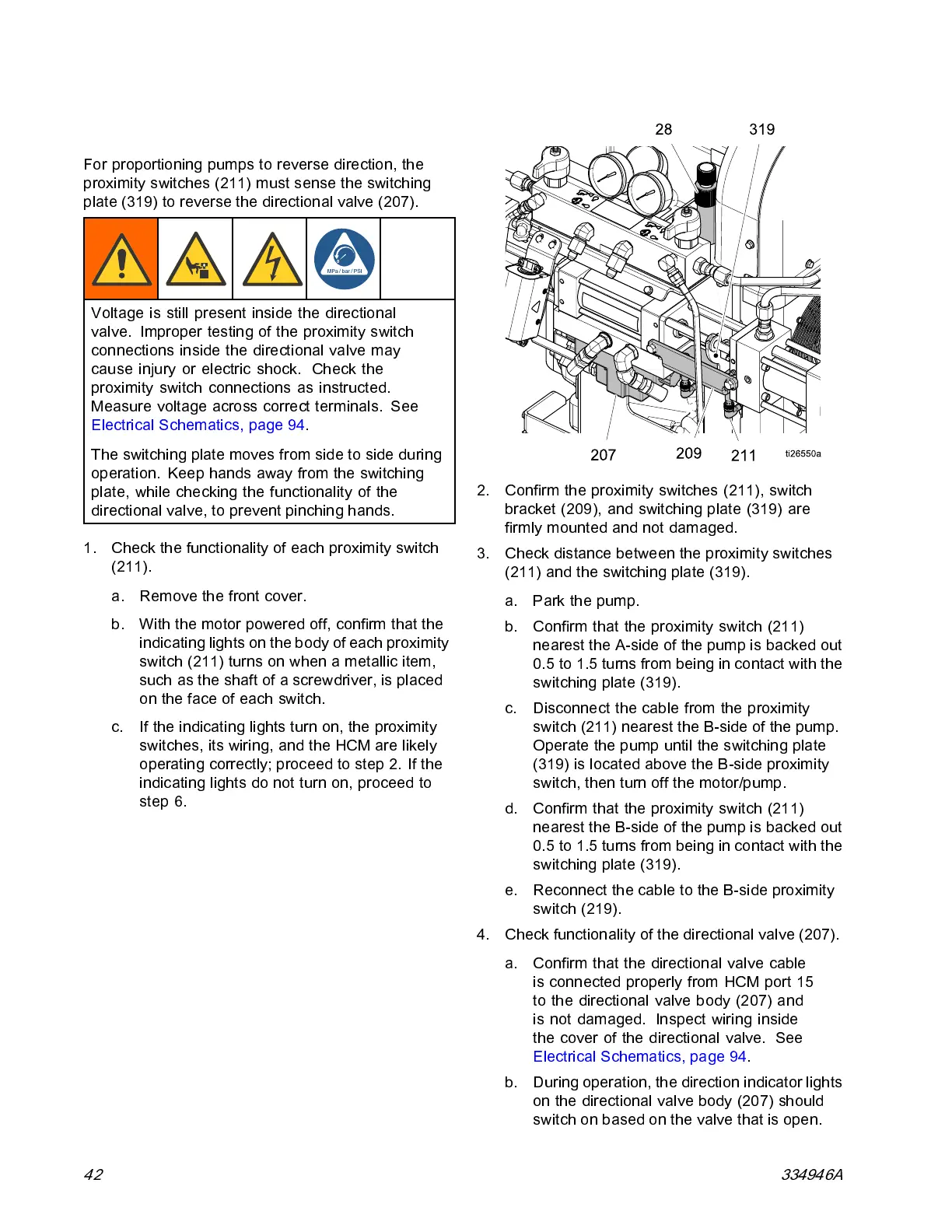
For proportioning pumps to reverse direction, the
proximity switches (211) must sense the switching
plate (319) to reverse the directional valve (207).
Voltage is still present inside the directional
valve. Improper testing of the proximity switch
connections inside the directional valve may
cause injury or electric shock. Check the
proximity switch connections as instructed.
Measure voltage across correct termi nals. See
Electrical Schem atics, page 94.
The switching plate moves from side to side during
operation. Keep hands away from the switching
plate, while checking the functionality of the
directional valve, to prevent pinching hands.
1. Check the functionality of each proximity switch
(211).
a. Remove t
he front cover.
b. With the
motor powered off, confirm that the
indicat
ing lights on the body of each proximity
switch (
211) turns on when a metallic item,
such as t
he shaft of a screwdriver, is placed
on the f
ace of each switch.
c. If the i
ndicating lights turn on, the proximity
switch
es, its wiring, and the HCM are likely
opera
ting correctly; proceed to step 2. If the
indic
ating lights do not turn on, proceed to
step 6
.
2. Confirm the proximity switches (211), switch
bracke t (209), and switching plate (319) are
firmly mounted and not damaged.
3. Check distance between the proximity switches
(211) and the switching plate (319).
a. Park the pump.
b. Confirm that the proximity switch (211)
nearest the A-side of the pump is backed out
0.5 to 1.5 turns from being in contact with the
switching plate (319).
c. Disconnect the cable from the proximity
switch (211) nearest the B-side of the pump.
Operate the pump until the switching plate
(319) is located above the B-side proximity
switch, then turn off the motor/pump.
d. Confirm that the proximity switch (211)
nearest the B-side of the pump is backed out
0.5 to 1.5 turns from being in contact with the
switching plate (319).
e. Reconnect the cable to the B-side proximity
switch (219).
4. Check functionality of the directional valve (207).
a. Confirm that the directional valve cable
is connected properly from HCM port 15
to the directional valve body (207) and
is not damaged. Inspect wiring inside
the cover of the directional valve. See
Electrical Schematics, page 94.
b. During op eration, the direc tion indicator l ights
on the directional valve body (207) should
switch on based on the valve that is open.
42
334946A