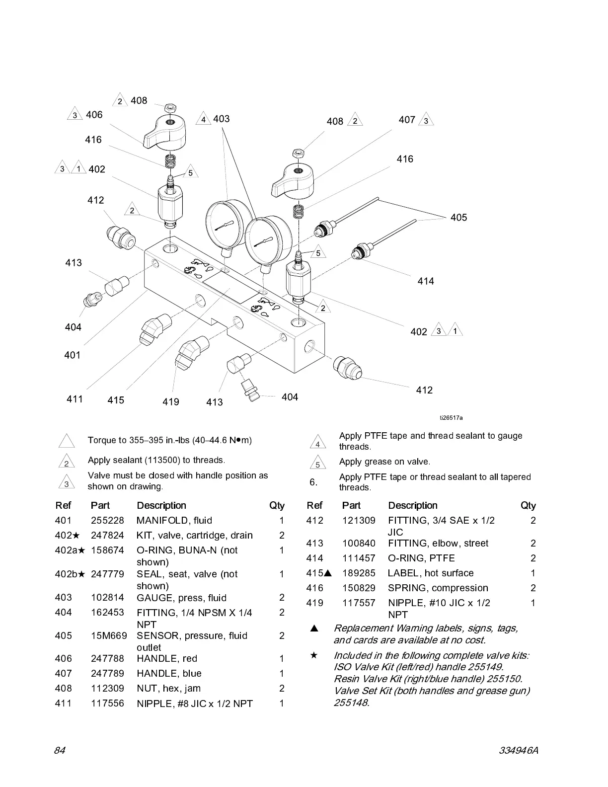
Parts
Fluid Manifold
1
Torque to 355–395 in.-lbs (40–44.6 N●m)
2
Apply sealant (113500) to threads.
3
Valve must be closed with handle position as
shown on drawing.
4
Apply PTFE tape and thread sealant to gauge
threads.
5
Apply grease on valve.
6.
Apply PTFE tape or thread sealant to all tapered
threads.
Ref
Part Description
Qty
401 255228
MANIFOLD, fluid
1
402
★
247824 KIT, valve, cartridge, drain 2
402a
★
158674
O-RING, BUNA -N (not
shown)
1
402b
★
247779 SEAL, seat, valve (not
shown)
1
403 102814
GAUGE, press, fluid
2
404 162453
FITTING, 1/4 NP SM X 1/4
NPT
2
405 15M669
SENSOR, pressure, fluid
outlet
2
406 247788 HANDLE, red 1
407 247789 HANDLE, blue 1
408 112309 NUT, hex, jam 2
411 117556
NIPPLE, #8 JIC x 1/2 NPT
1
Ref
Part Description
Qty
412 121309
FITTING, 3/4 SAE x 1/2
JIC
2
413 100840 FITTING, elbow, street 2
414 111457 O-RING, PTFE 2
415
▲
189285 LABEL, hot surface 1
416 150829 SPRING, compression 2
419 117557 NIPPLE, #10 JIC x 1/2
NPT
1
▲
Replacement Warning labels, signs, tags,
and cards are available at no cost.
★
Included in the following complete valve kits:
ISO Va lve Kit (left/red) handle 255149.
Resin Val ve Ki t (right/bl ue han dl e) 25515 0.
Valve Set Kit (both handles and grease gun)
255148.
84 334946A