Troubleshooting
c. Turn on the motor and stall the pumps at the
lowest pressure setting (compensator knob
turned fully counter-clockwise). The pump
will travel in either the A or B direction until
the pressure setting is reached.
d. Identify the solenoid that is operating by
viewing the direction indicator lights on the
cover of the directional valve (207). Measure
voltage across the associated terminals to
determine if proper voltage is reaching the
valve (approximatel y 200 to 240 VAC). See
Electrical Schematics, page 94,andthetable
below, to identify the proper terminals to
measure across.
e. Trigger each proximity switch (211) with
the shaft of a screwdriver, confirming each
solenoid within the directional valve (207)
operates as described in table below.
f. If one or both sides are not operating
properly, according to the table, first
reconfirm wirin g to directional valve (207) per
Electrical Schematics, page 94, then replace
directional valve (207).
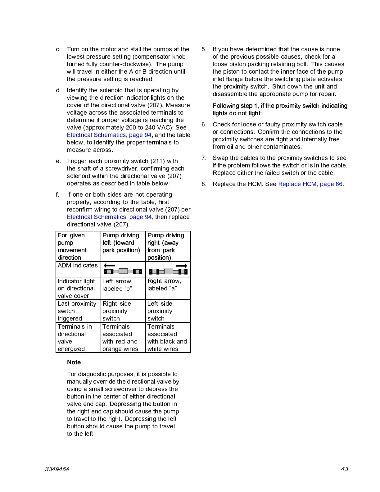
For given
pump
movement
direction:
Pum p driving
left (toward
park position)
Pump drivi ng
right (away
from park
position)
ADM ind icate s
Indicator light
on directional
valve cover
Left arrow,
labeled “b”
Right arrow,
labeled “a”
Last proximity
switch
triggered
Right side
proximity
switch
Left side
proxim ity
switc h
Terminals in
directional
valve
energized
Termin als
associated
with red and
orange wires
Terminals
associated
with black and
white wires
Note
For diagnostic purposes, it is possible to
manually override the directional valve by
using a small screwdriver to depress the
button in the center of either directional
valve end cap. Depressing the button in
the right end cap should cause the pump
to trave l to the right. Depressing the left
button should cause the pum p to travel
to the left.
5. If you have determined that the cause is none
of the previous possible causes, check for a
loose piston p acking retaining bolt. This causes
the piston to contact the inner face of the pump
inlet flange before the switching plate activates
the proximity switch. Shut down the unit and
disassemble the appropriate pump for repair.
Following step 1, if the proximity switch indicating
lights do not light:
6. Check for loose or faulty proximity switch cable
or connections. Confirm the connections to the
proximity switches are tight and internally free
from oil and other contaminates.
7. Swap the cables to the proximity switches to see
if the problem follows the switch or is in the cable.
Replace either the failed switch or the cable.
8. Replace the HCM. See Replace HCM, page 66.
334946A 43