Repair
Replace Fluid Inlet Sensor
See Flu id Inlet Sensor Kit 17F837 manual 3A3009.
1. Flush. See Flushing, page 51.
2. See Shutdown, page 50.
3. Disconnect inlet sensor cable from the fluid inlet
assembly. Inspect cable for damage and replace
if necessary. See Electrical Schematics, page 94.
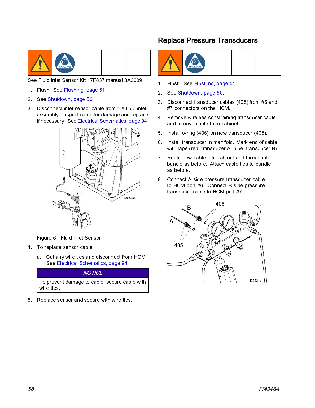
Figure 6 Fluid Inlet Sensor
4. To replace sensor cabl e:
a. Cut any wire ties and disconnect from HCM.
See Electrical Schematic s, page 94.
NOTICE
To prevent damage to cable, secure cable with
wire ties.
5. Replace sensor and secure with wire ties.
Replace Pressure Transducers
1. Flush. See Flushing, page 51.
2. See Shutdown, page 50.
3. Disconnect transducer cables (405) from #6 and
#7 connectors on the HCM.
4. Remove wire ties constraining transducer cable
and remove cable from cabinet.
5. Install o-ring (406) on new transducer (405).
6. Install transducer in manifold. Mark end of cable
with tape (red=transducer A, blue=transducer B).
7. Route new cable into cabinet and thread into
bundle as before. Atta ch cabl e ties to bundle
as before.
8. Connect A side pressure transducer cable
to HCM port #6. Connect B side pressure
transducer cable to HCM port #7.
58 334946A