Repair
3A1570V 27
5. Loosen two screws (314) behind air motor bracket.
Carefully lift air motor and tie rods away from the
proportioner frame and plate (301).
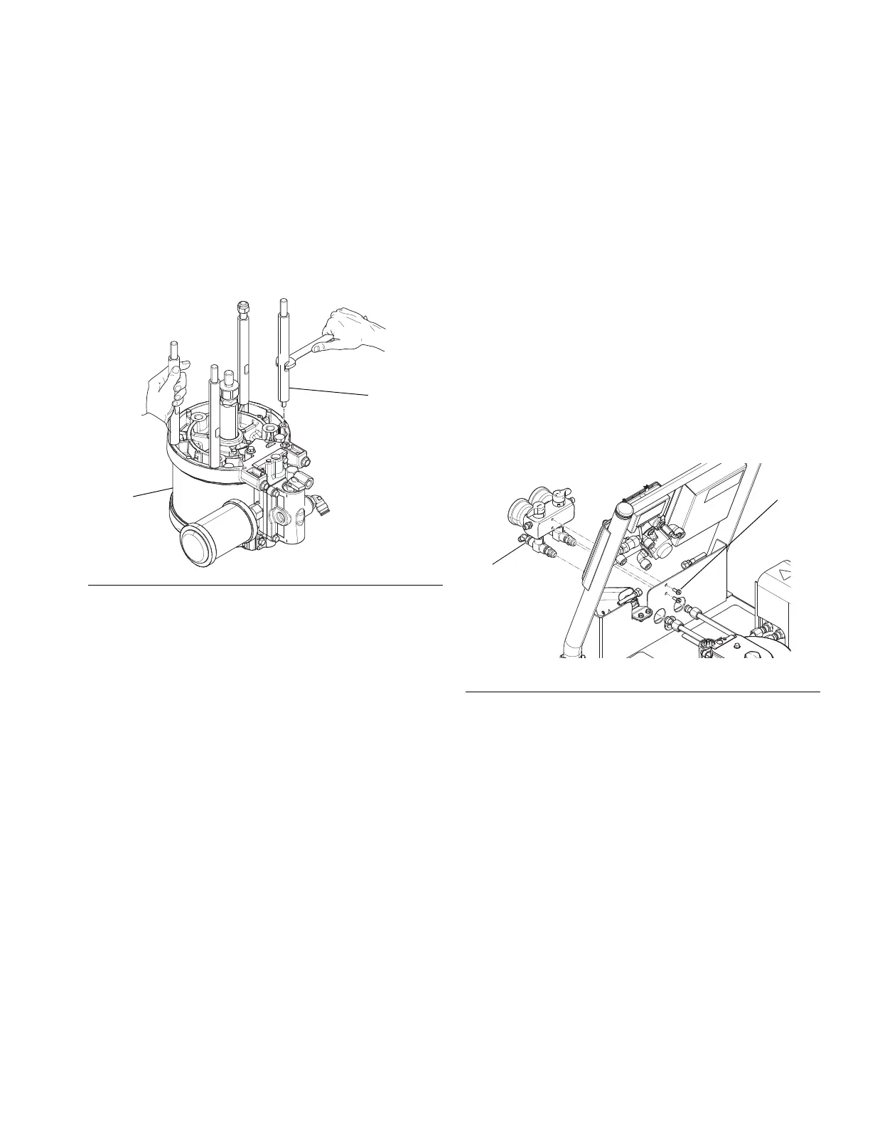
6. Lay air motor on a clean flat work space. Place a
wrench on the tie rod flats (309) and hold one of
other tie rods with your hand to keep the air motor
(308) in place. Remove the tie rods from the air
motor.
7. Use a wrench to hold the piston rod in place and
remove the adapter (315) with another wrench. See
F
IG
. 1.
8. See air motor manual for repair instructions.
Install Air Motor
1. Apply medium blue thread lock on adapter (315).
Use a wrench to hold the piston rod in place and
install the adapter (315) with another wrench.
Torque to 32-38 ft-lbs (43-51 N•m). See F
IG
. 1.
2. Install tie rods (309) in the bottom of the air motor
(308). See F
IG
. 3.
3. Install tie rods through plate (301). Ensure screws
(314) fit in the bracket slots (311). Install screws
(314). See F
IG
. 2.
4. Tighten nut (313) to 32-38 ft-lbs (43-51 N•m).
5. Evenly torque four tie rod nuts (310) in small
increments to 27-32 ft-lbs (37-43N•m). See F
IG
. 2.
Recirculation / Over Pressure
Relief Block
Valves can be serviced with the block on the machine
(see Fluid Manifold, page 50 for parts view). For
thorough cleaning, remove the block assembly as
follows.
1. Disconnect two fluid tubes connected to back of
recirculation block (3).
2. Loosen and remove two screws (10) in back of
recirculation block.
3. See Fluid Manifold, page 50. Clean and inspect all
parts for damage. Ensure that the seat (8a) and
gasket (8b) are positioned inside each valve
cartridge (8).
4. Apply PTFE pipe sealant to all tapered pipe threads
before reassembling.
5. Reassemble in reverse order, following all notes in
Fluid Manifold, page 50.
F
IG
. 3
F
IG
. 4