Repair
309574C 35
Temperature Sensor
2. Relieve pressure, page 8.
3. Wait for heaters to cool.
4. Disconnect temperature sensor wires from J1 on
temperature control board. See T
ABLE
4, page 32
and F
IG
. 10, page 33.
5. See F
IG
. 12. Test with ohmmeter. Between wires
(S), resistance must be approximately 6 ohms.
Between tip (T) and wires, resistance must be infin-
ity (∞).
6. If sensor fails test, feed wires out of cabinet. Note
path as wires must be replaced in the same way.
7. Loosen ferrule nut (N) and remove temperature sen-
sor (211) from heater tube (201).
8. Replace sensor, F
IG
. 12.
a. Remove protective tape from sensor tip (T).
b. Apply tape and thread sealant to male
threads and tighten sensor housing (H) into
tube (201).
c. Push in sensor so tip (T) contacts heater ele-
ment (207), avoiding mixer (202).
d. Tighten ferrule nut (N), holding sensor (T)
against heater element.
9. Route wires into cabinet and thread into bundle as
before. Reconnect wires to board.
10. Turn on heaters A and B simultaneously to test.
Temperatures should rise at same rate (30°F, + / - 4 °).
If one heater is low, loosen ferrule nut (N) and
tighten sensor housing (H) to ensure sensor tip (T)
contacts element (207).
1. Turn main power OFF . Disconnect power
supply.
WARNING
Read warnings, page 6. Wait for heaters to cool before
repairing.
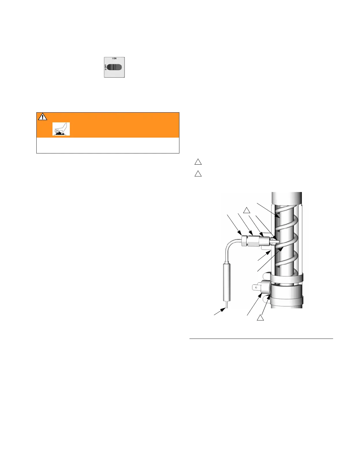
F
IG
. 12. Temperature Sensor
202
201
S
NH T
207
Apply tape and thread sealant.
1
1
208
TI3249a
Apply 110009 thermal heatsink compound.
2