Commissioning
48
10.3.3 Heat Exchangers
To gain access to the top of both heat
exchangers:
• Remove the boiler top casing panel.
• Unscrew and remove the two nuts
securing the front access panel and
remove it from the primary heat
exchanger.
• Unscrew and remove the two nuts
securing the rear access cover and
remove it from the secondary
(condensing) heat exchanger.
Check that the spiral baffles in the
primary heat exchanger are all in place.
Lift and drop each one to check all are
free to move in their respective tubes.
Check that the spiral baffles in the
secondary heat exchanger are all in
place and are all aligned with the top
edges running ‘front to back’.
Test the automatic cleaning functions as
follows:
• Set the ON/STANDBY switch to
STANDBY.
• Switch on the electrical supply to
the hopper and boiler. The burner
fan should briefly run.
• Press and hold down the
‘CLEANING’ switch, on the boiler
control panel, in the ‘TEST’ position.
• Release switch to automatically
reset cleaning function back to
‘AUTO’.
• Note that setting this switch to
‘TEST’ does NOT operate the
burner cleaning function, but only
that of the two heat exchangers.
Primary Heat Exchanger
Check the shaker unit (located in the
top of the primary heat exchanger) is
operating freely and that the spirals are
moving up and down with two
intermittent vertical motions.
Secondary Heat Exchanger
Check the wash system manifold
(located under the top rear access
door) is spraying water directly into
each flue gas tube of the unit. Refer to
Figure 10-4.
If the water jets are not spraying directly
into the flue gas tubes, adjust the spray
as follows:
• Slacken the two screws securing
the manifold pipe flange to the
boiler side panel.
• Carefully rotate the pipe until jets
spray directly into tubes.
• Tighten the two screws to secure
manifold pipe in this position.
Refit both front and rear access panels
and secure with the nuts previously
removed. Do not overtighten.
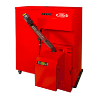
10.4 Pellet Hopper
Check the pellet feed auger is fully
inserted into the pellet hopper and
secured with the single screw through
the auger fixing flange. Refer to Figure
10-6. Do NOT fill hopper with pellets
until AFTER the auger is fitted and
secured.
Ensure that only pellets that comply
with ENplus A1 standard, to EN14961,
are used with the Grant Spira boiler.
Refer to Section 3.
Fill the hopper with pellets either:
• By hand from bags, or
• Automatically from a bulk pellet
store, via a bulk auger or Grant
SPIRA-VAC vacuum pellet feed
system.
When using a Grant SPIRA-VAC
system, refer to the Installation
instructions supplied with the Grant
SPIRA-VAC vacuum pellet feed system.
10.5 Safety Device Checks
10.5.1 Burn Back Thermostat
When the burner display reads ‘WAIT
BOILER THERMOSTAT’ check the
operation of the burn-back thermostat
(on the pellet feed tube) as follows:
• Remove the steel clip from the
thermostat.
• Disconnect the lead from the
thermostat terminals. Refer to
Figure 10-7.
10 Commissioning
Figure 10-3: Combustion chamber
baffle
Figure 10-4: Correct jet spray (into
tubes)
Figure 10-5: Incorrect jet spray
Figure 10-6: Auger fixing
Ensure that fingers are clear of all
moving parts inside the top of the
primary heat exchanger BEFORE
operating ‘CLEANING TEST’ switch.
!
WARNING
Before filling the pellet hopper for
the first time with pellets, ensure that
hopper is empty of all other debris or
objects, e.g. screws, nuts, etc.
!
WARNING

 Loading...


