Boiler Servicing
53
11 Boiler Servicing
11.1 General
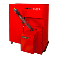
It is essential that the Grant Spira boiler
is serviced at regular intervals of no
longer than 12 months OR when the
‘SERVICE’ is shown on the burner
control panel display.
The burner will automatically indicate
‘SERVICE’ on the burner control panel
display once the pre-set period of pellet
feed auger run time (‘HOURS
SERVICE’) is achieved. Refer to
Section 9.7 for details on how to
access and check this setting in the
‘INSTAL CLEAN’ sub-menu of the
burner settings.
This interval is based on the auger
running time, i.e. the actual quantity of
pellets used based on the pellet feed
auger rate and pellet delivery settings.
Refer to Section 9.7 for details on how
to access and check this setting in the
‘POWER PELLET’ sub-menu of the
burner settings.
The ash pan (located inside the
combustion chamber) will need to be
periodically emptied. This simple task
must be carried out by the user at
MONTHLY intervals for the FIRST
THREE MONTHS. Thereafter, the ash
pan should be emptied regularly, on at
least a monthly basis, or as indicated
by the amount of ash found during the
first three months. Two carrying handles
are supplied with the boiler to allow
removal of the ash pan when hot.
Servicing and replacement of parts
must only be carried out by a Grant
Approved installer who has successfully
completed the Grant Spira wood pellet
boiler training course.
11.2 Checks Before Servicing
BEFORE starting any service work on
the boiler or pellet storage/supply
installation:
• Set the ON/STANDBY switch, on
the boiler control panel, to
STANDBY. If the boiler was
operating, wait for it to shut-down
and ‘WAIT BOILER THERMOSTAT’
is shown on the burner control
panel display before proceeding
further.
• Isolate the electrical supply to the
hopper and boiler and remove the
5A fuse from the fused spur.
• Disconnect the 5-way plug (on the
lead from the hopper) from the
socket at the left rear of the boiler.
Refer to Figure 11-1.
• If a double boiler installation, remove
the 5-way plug from both boilers.
• Disconnect the 5-way plug (on the
lead from the flue fan and solenoid)
from the socket at the right rear of
the boiler. Refer to Figure 11-2.
This will allow the hopper to be moved
to give easy access to the rear of the
boiler for servicing.
11.3 Heating System
If boiler is part of a sealed heating
system, check the following:
• System pressure
• Pressure relief valve operation
• Expansion vessel air charge pressure
(when the system pressure is zero)
Check the boiler for any indication of
leaks from:
• Flow and return connections
• Automatic air vent (at rear of boiler)
• Drain cock (at lower rear of boiler)
Remake any joints and re-check
tightness of any fitting that may be
leaking.
Re-fill and vent the system to the
required pressure. Refer to Section 6.
On either sealed or open-vented
systems:
• Inspect and clean the in-line
magnetic filter in accordance with
the filter manufacturer’s instructions.
• Ensure that adequate corrosion
protection is present in system.
11.4 Flue System
11.4.1 Flue Terminal
Check the flue terminal and ensure that
it is not blocked or damaged.
11.4.2 Fan Box
Unscrew the eight screws securing the
flue inspection plate on to the fan box
and remove the plate. Inspect inside of
both flue and fan box. Refer to Figure
11-3. Clean any ash deposits from the
inside of the fan box, as necessary.
Clean the flue by sweeping, as required.
Replace plate and secure using the
eight screws, ensuring that it is
correctly sealed to the fan box on the
neoprene gasket.
!
NOTE
Details of every service should be
entered in the Service log at the front
of this manual.
Before starting any work on the
boiler, or on the pellet storage and
supply installation, please read the
health and safety information in
Section 15.
!
WARNING
Figure 11-2: Disconnecting fan
5-way plug
Figure 11-3: Fan box inspection
opening
Figure 11-1: Disconnecting hopper
5-way plug

 Loading...


