Page 16
4.8 INSTALLING THE BOILER
1. If the boiler is to be tted against a wall, prepare the wall to
accept the heating system pipework. To mark the wall for
drilling, refer to Section 2.6 for the positions of the pipework
openings in the enclosure sides.
! NOTE !
Pipework should be insulated where it passes through the
wall into the boiler enclosure.
If the boiler is to be installed ‘free standing’ (i.e. away from
a wall) and the pipework run underground, push out the
‘knock-outs’ to open the required pipe openings in the base
of the boiler enclosure. Using a sharp knife, cut through the
polystyrene in the base, around the edge of the holes, to
allow the ow and return pipes to enter the enclosure.
2. The electrical supply to the boiler should be routed through
the wall in a suitable conduit, such that it enters the boiler
enclosure via one of the unused pipework openings. The
cable can be routed to the front of the boiler, for connection
to the boiler control panel, either over the top or beneath
the boiler heat exchanger. Heat resistant PVC cable, of
at least 0.75mm² cross section should be used within the
boiler enclosure. Refer to Section 8 for further information
regarding the electrical side of the installation process.
! NOTE !
Pipework and cables can be routed into the enclosure via
one of the unused ue exit holes by using a section of
110mm soil pipe as ducting through the wall. The ue exit
holes in the boiler casing are sized to accept 110mm soil
pipe.
3. The oil supply line should be installed up to the position
of the boiler. Refer to section 3.1 for details. The nal
connection into the boiler enclosure can be made with 10mm
soft copper, routed along the base of the enclosure (either
between the enclosure and wall or in front of the enclosure)
to enter through one of the holes located in the bottom edge
side panel, at the front (burner) end.
4. Connect the power supply as described in Section 8.
5. Ensure the ue terminal postion complies with the necessary
clearances outlined in Section 9.
4.9 FILLING THE HEATING SYSTEM
Refer to Section 7.2 (Filling the Sealed System)
4.10 BEFORE YOU COMMISSION
To avoid the danger of dirt and foreign matter entering the boiler
the complete heating system should be thoroughly ushed
out – both before the boiler is connected and then again after
the system has been heated and is still hot. This is especially
important where the boiler is to be installed on an older system.
For optimum performance after installation, the boiler and the
associated heating system must be ushed in accordance with
the guidelines given in BS 7593 (Treatment of water in domestic
hot water central heating systems). This must involve the use
of a proprietary cleaner, such as Sentinel X300 (new systems),
Sentinel X400 (existing systems), or Fernox Restorer.
After cleaning, it is vitally important that all traces of the cleaner
are thoroughly ushed from the system.
For long term protection against corrosion and scale, after
cleaning/ushing a suitable inhibitor should be added to the
system water, such as Sentinel X100 or Fernox MB-1, in
accordance with the manufacturers’ instructions.
Failure to follow the above will invalidate the guarantee.
If the boiler is installed in a garage, out house or outside, in order
to provide further protection should there be a power failure in
cold weather, a combined anti-freeze and corrosion inhibitor can
be used such as Sentinel X500 or Fernox Alphi-11. Follow the
manufacturers’ instructions supplied to achieve the level of anti-
freeze protection required.
For details of the Sentinel Products visit www.sentinel-solutions.
net and for Fernox products visit www.fernox.com.
Grant UK strongly recommends that a Grant Mag One in-line
magnetic lter/s (or equivalent*) is tted in the heating system
pipework. This should be installed and regularly serviced in
accordance with the lter manufacturer’s instructions.
* As measured by gauss. The MagOne magnetic lter has a gauss
value of 12000.
4.11 COMPLETION
Following installation of the boiler, instruct the user in the
operation of the boiler, the boiler controls, the heating controls and
the safety devices.
Please ensure that the OFTEC CD/10 installation completion
report (provided with the boiler) is completed in full, leaving the
top copy with the user and retain the carbon copy for your own
records.
Ensure that the User Handbook (supplied with the boiler) is
handed over to the user.
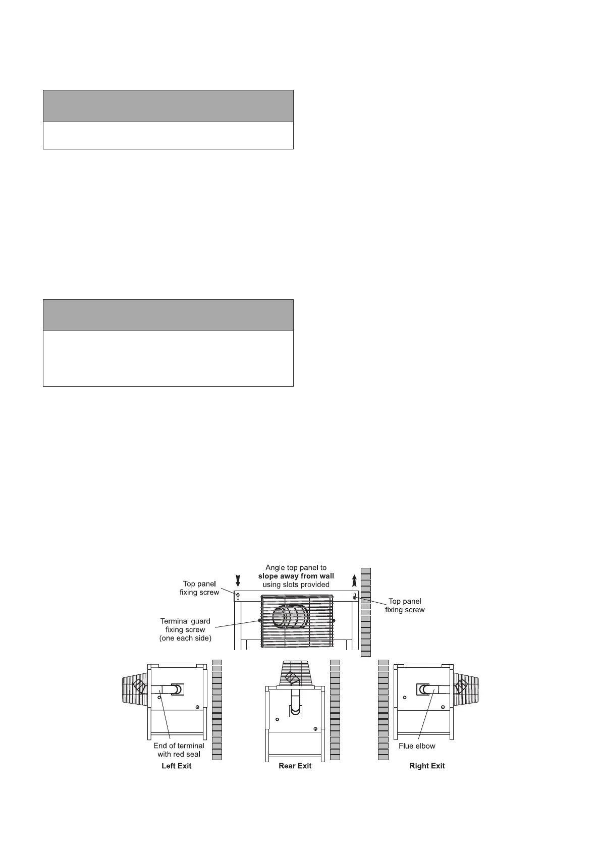
Figure 4-1: Standard low level ue provided with Outdoor Module
Section 4: Installation