Page 32 Section 9: Flue System and Air Supply
9.3 CONVENTIONAL FLUE SYSTEMS
! NOTE !
Under no circumstances can Grant Vortex boilers be
installed with existing ue systems. Only ue systems and
components suitable for wet ues should be used.
Failure to install the correct type of ue system will
invalidate the guarantee.
Grant condensing boilers have high operating eciencies and
low ue gas temperatures. Care must be taken to ensure the
ue system is suitable for the very low ue gas temperatures and
condensate in the ue gases.
Suitable conventional ue systems are available from Grant UK.
The ue must terminate in a down draught free area, i.e. at least
600 mm above the point of exit through the roof or preferably
above the ridge level.
The condensate may be allowed to run back into the boiler. A
condensate drain at the base of the ue system is not required.
The high level ue terminal must be at least 600 mm from
any opening into the building, and 600 mm above any vertical
structure or wall less than a horizontal distance of 750 mm from
the terminal.
More detailed information on the siting of the ue terminal can be
found in Figure 9-5 and Table 9-3.
The internal ue and liner diameter for all models up to 46kW
output must be 100 mm (4 in) and for the 46/58 and 58/70 models
125mm (5 in).
Twin wall ues are recommended for externally run ues to
reduce the possibility of the condensate freezing in the ue.
No part of any ue system should be made of an asbestos
material; aluminium must not be used in any part of the ue. Only
stainless steel ue components should be used.
If the draught conditions are satisfactory, the ue should terminate
with a standard cowl.
Refer to the locally applicable Building Regulations, BS 5410-1
and OFTEC Installation Requirements (OFTEC Books 2 and 3)
for further guidance on conventional ue systems.
! CAUTION !
It is important to ensure that the ue system is sealed and
that condensate cannot escape. Up to 1.5 l/h of condensate
can be produced in a conventional ue system.
Do not use re cement. The use of high temperature
silicone sealants is recommended.
! NOTE !
To comply with the requirements of the Building
Regulations Approved Document J - conventional ue
systems must have a ue data plate.
9.4 EXTERNAL VERTICAL CONVENTIONAL
FLUE (GREEN SYSTEM)
The external system can terminate at either high level or vertically
(above roof level) as required. The vertical or high level terminal
must terminate in accordance with BS 5410-1. The minimum
dimensions for locating the high level terminal from building
features (windows, doors, etc.) are shown in Figure 9-5 and Table
9-3.
The Green system comprises of ve insulated extension lengths,
45° elbows, a vertical terminal and a high level horizontal terminal.
Locking bands are provided with all vertical extensions and
terminals. Ensure that the locking bands are tted.
Two types of wall bracket are also available (standard and
adjustable) to support the vertical ue components.
The maximum vertical height (from the top of the boiler to the
terminal) for the ‘Green’ system twin wall ue is 19 metres. Only
two 45° elbows may be used in the complete system.
If the ue terminal is tted less than 2 metres above a surface to
which people have access, the terminal must be protected by a
guard. The guard must be manufactured from stainless steel and
should be tted centrally over the ue terminal and securely xed
to the wall.
CONNECTION OF VERTICAL GREEN FLUE
SYSTEM
1. Connect Grant Green system to the boiler ue outlet using
the Grant Green system External Module starter elbow
(product code: GKM90 for models up to 26kW or GKM200 for
models ranging from 26-70kW).
2. Fit the starter elbow into the boiler connector after rst
ensuring that the seal is in place in the connector.
! NOTE !
Lubricate the seal on the boiler connector using the
lubricant provided before attempting to t the starter piece.
Ensure that seals in all ue sections are lubricated before
installing.
3. Assemble the remainder of the ue system as required,
lubricating the seal on each component before tting and
securing every joint with the locking band provided.
The external vertical ue (Green system) components available
from Grant UK can be found in Figure 9-3 and Table 9-2.
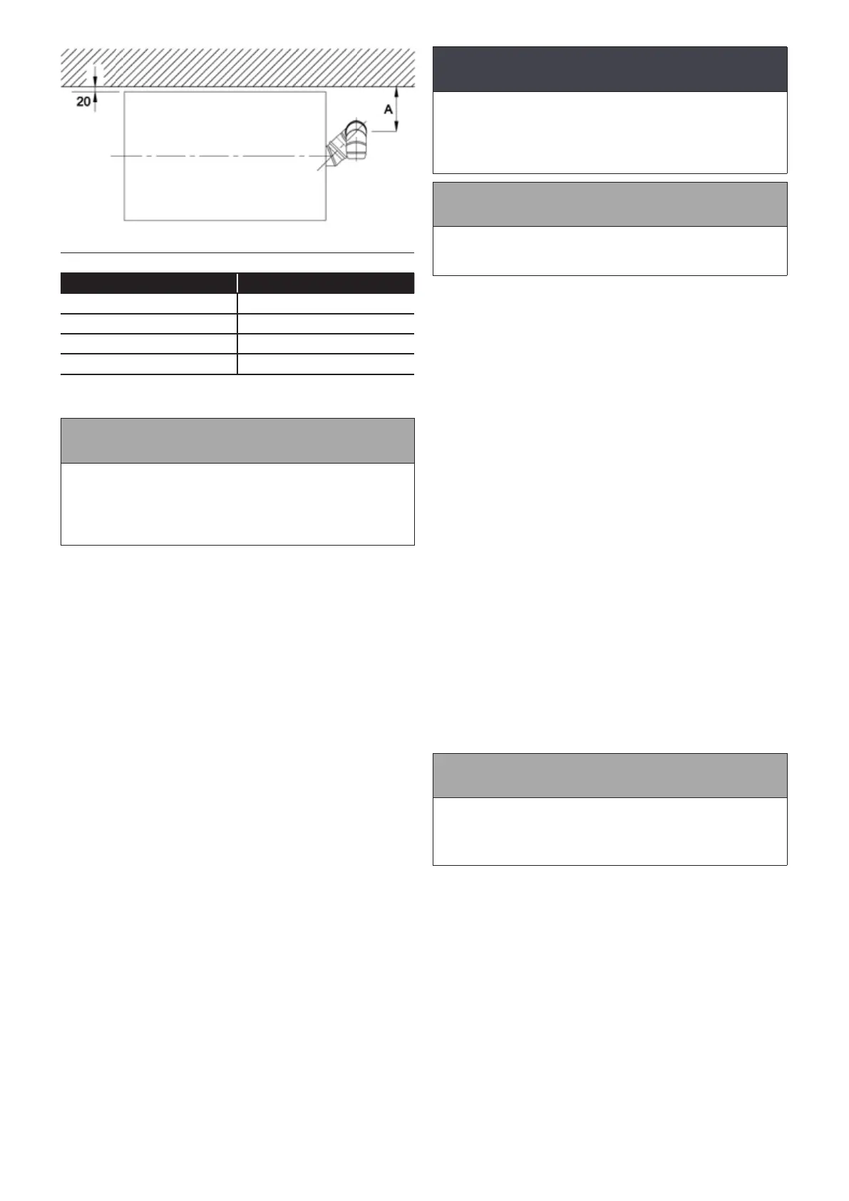
Table 9-1: Distance of plume diverter centre from external wall
Model Dimension A (mm)
15/21 115
15/26 177
26/36 & 36/46 150
46/58 & 58/70 188
Figure 9-2: Plume diverter kit - Plan View