5.1 WATER CONNECTIONS
The ow and return pipework can exit the boiler enclosure either
through the pre-cut openings provided in both sides (under the
movable cover plates) and through the wall when installed against
the building, down and through the pre-cut openings provided
in the base of the enclosure for ‘free standing’ installations, or
through an unused side ue exit opening (the ue exit holes in the
side of the boiler casing are sized to accept a 110mm soil pipe to
be used as a pipe duct through the wall). See Section 2.6.
Push out the ‘knock-out’ from the required holes, taking care not
to distort the side panel or base.
For condensate disposal pipework refer to Section 6.
1. To gain access to the water connections, remove the two
screws securing the bottom of the back panel and remove
it by withdrawing it forwards at the bottom. Remove the top
casing panel.
2. Fit the ue starter elbow in the chosen position. This should
be done at this point to ensure the starter elbow will not
conict with any of the pipework. Refer to Sections 4.7 and 9.
3. If required, t the Grant sealed system kit. Refer to Section 7.
4. Carefully manoeuvre the boiler in position to line up with
pipework through the wall. Complete the water connections.
Note: Check that the baes are in position and that the
cleaning cover is correctly tted and a good seal made.
5. If the boiler is installed against a wall, t the wall ashing
strip. Position the strip with the bottom edge of the wider
ange 20 mm above the enclosure top panel, with the narrow
ange (with the three xing holes) at against the wall. The
strip should overhang the top panel by an equal amount at
each end.
6. Mark the position of the three xing holes onto the wall, drill
and plug the wall and secure the strip with suitable screws
(not supplied).
15/21, 15/26, 26/36, 36/46 Flow connection: A pipe (22 mm for
15/21, 15/26 or 28 mm for 26/36, 36/46) is provided for the ow
connection. This is located on the top of the boiler. The pipe will
need to be vented, as it is the highest point on the primary heat
exchanger.
15/21, 15/26, 26/36, 36/46 Return connection: A pipe (22 mm for
15/21, 15/26 or 28 mm for 26/36, 36/46) is provided for the return
connection. This is located on the top of the boiler. The pipe will
also need to be vented at some point, as it is the highest point on
the secondary heat exchanger.
46/58, 58/70 Flow connection: A 1¼” BSP socket is provided for
the ow connection. This is located on the top of the boiler. This
ow pipe will need to be vented, as it is the highest point on the
primary heat exchanger.
46/58, 58/70 Return connection: A 1¼” BSP socket is located
on top of the boiler. This return pipe will also need to be vented
at some point, as it is the highest point on the secondary heat
exchanger.
! CAUTION !
All pipes to be tted into the push-t connectors provided
should be cut using a pipe slicer or pipe cutter - to leave
the pipe ends with a slight radius and free from any burrs
or sharp edges. Pipes to be used with these ttings should
not be cut square using a hacksaw.
5.2 WATER CONNECTIONS AND
THERMOSTAT PHIAL POSITIONS
Section 5: Pipe Connections Page 17
5 PIPE CONNECTIONS
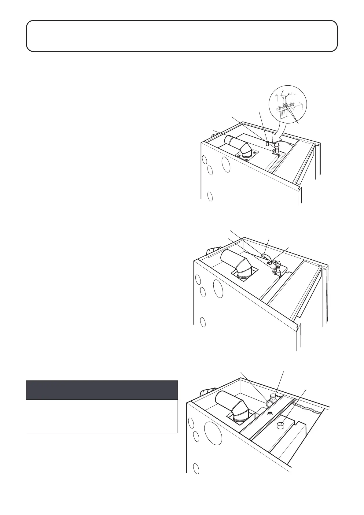
Figure 5-1: 15/26 water connections
Heating return
Heating flow
Thermostat phials
Air Vent
Heating flow
Thermostat phials
Heating return
Air Vent
Heating return
Thermostat phials
Heating flow
Figure 5-2: 15/21, 26/36, 36/46 water connections
Figure 5-3: 46/58, 58/70 water connections