Page 65
Appendix A2: Wilo-PARA 25-130/7-50/SC-6#GRA
APPENDIX A2 WILO-PARA 25-130/7-50/SC-6#GRA
CIRCULATING PUMP
A2.1 WILO-PARA 25-130/7-50/SC-6#GRA
CIRCULATING PUMP
A2.1.1 PUMP SPECIFICATION
Table A2-1: Pump specication
Make and model
Wilo - PARA 25-130/7- 50/SC-
6#GRA
Construction
Pump housing
Cast iron (with cataphoresis
treatment)
Impellar PP composite with GF 40%
Pump shaft Stainless Steel
Bearing Carbon, metal impregnated
Motor Data
Speed 2580 - 4700rpm
Power consumption @ 1 - 230V 8.2 - 50W
Current @ 1 - 230V 0.07 - 0.43A
Minimum starting voltage 170V
Minimum running voltage 160V
Peak inrush current >3A
Starting torque >25N.cm
Electrical
Mains connection 1ph 230V AC +10%/-15% 50/60Hz
Protection Class IPx4D
Insulation Class F
Motor Protection Integrated
Performance
Max. delivery head 7.7m @ Q = 0 m
3
/h
Max. volume ow 3.5 m
3
/h
Minimum suction head @ 50/95°C 0.5/4.5m
Energy Eciency Index (EEI) ≤ 0.20
Settings
∆P-variable (1-7m head)
∆P-constant (1-7m head)
Constant Speed (I, II and III)
Application
Maximum Static Pressure PN10
Fluid Temperature range @
maximum ambient temperatures
(See Section A2.1.2)
Maximum ambient temperature
58°C: 0 to 100°C
Maximum ambient temperature
62°C: 0 to 90°C
Maximum ambient temperature
66°C: 0 to 80°C
Maximum ambient temperature
71°C: 0 to 70°C
Approved Fluids
Heating Water
Water/Glycol - Max 1:1 (above 20%
check pumping data)
1
2
3
4
5
8
9
10
7
6
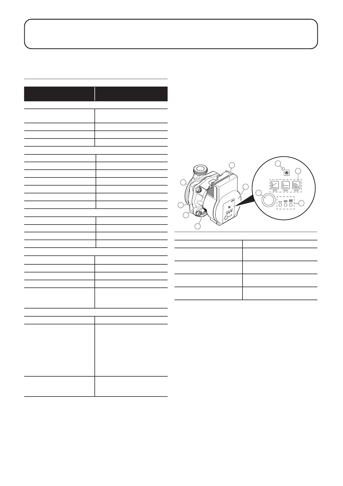
Figure A2-1: Pump components and control panel
1. Pump housing 6. Rating plate
2. Glandless motor 7. Operating button for pump
adjustment
3. Condensate drain openings
(4 around motor)
8. Run/Fault signal LED
4. Housing screws 9. Display of selected control
mode
5. Control module 10. Display of selected pump
curve (I, II, III)
A2.1.3 PUMP COMPONENTS
A2.1.4 CONTROL PANEL
Indicator LEDs
• Run/Fault signal LED (item 8, Figure A2-1)
- LED is GREEN when pump is running in normal pump
operation.
- LED lights up red/ashes when there is a fault (refer to
Section A2.2).
• Control mode display LEDs (item 9, Figure A2-1)
• Pump curve display LEDs (item 10, Figure A2-1)
• LED combinations are used to indicate when the following
functions are in operation:
- Pump venting (refer to Sections A2.1.5 and A2.1.6 for
information on how to activate this function).
- Manual restart (refer to Sections A2.1.5 and A2.2 for
information on how to activate this function).
- Key lock (refer to Sections A2.1.5 and A2.1.6 for
information on how to activate this function).
A2.1.2 THERMAL PROTECTION FUNCTION
The pump is equipped with a thermal self-protection mode.
If the uid temperature exceeds the maximum value at a specic
ambient temperature, e.g. 90°C at an ambient of 62°C, the pump
will automatically reduce the power consumption, reducing the
speed and performance of the pump.
In this condition the Run/Fault signal LED will be blinking RED.
When normal temperature conditions return the pump will
automatically revert to normal operation.
If the uid temperature increases further, the thermal protection
function may stop the pump temporarily.
In this condition the Run/Fault signal LED on the pump will be
constant RED until normal temperature conditions return.