Page 25
9. Remove the right hand boiler casing panel (viewed from the
burner end). This panel is xed in place by:
• Two screws in the right end of the upper rear panel.
• Four screws along the lower outer edge of the side panel.
• Two screws at the right end of the control panel.
Note: It will be necessary to support the control panel when
the side panel is removed.
10. Slacken the compression nut at the base of the ow connection
pipe (on the right hand side of the boiler). Carefully rotate the
ow pipe through 180° until it faces to the front of the boiler, then
re-tighten the compression nut.
11. Push the 28 mm push-t connector (supplied with the boiler)
onto the end of the boiler ow pipe.
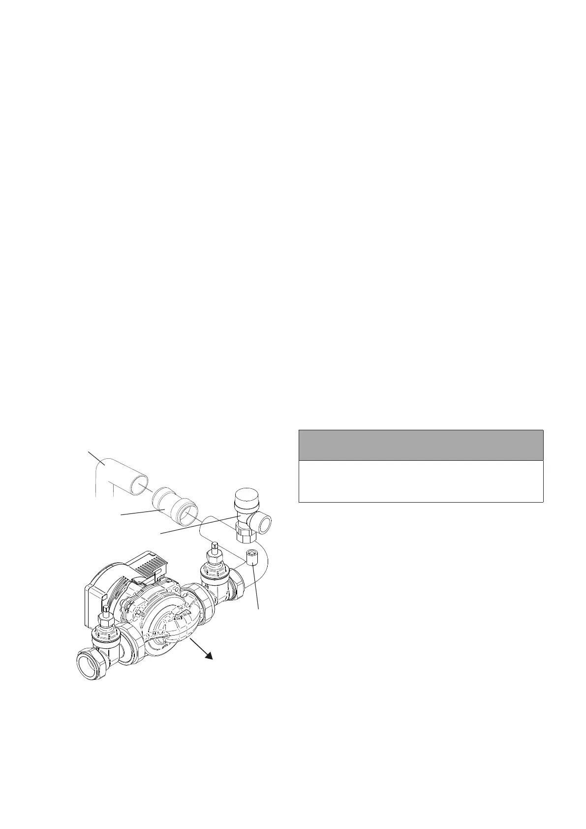
12. Fit the pressure relief valve onto the manifold pipe, then push
the manifold pipe end into the 28 mm push-t elbow on the
ow pipe. Refer to Figure 7-9.
13. Remove the two screws securing the motor to the pump body.
Rotate the motor through 180°, then replace and secure with the
two screws. Fit both 28 mm pump valves to the pump using the
sealing washers supplied.
14. Fit the pump assembly to the air vent/pressure relief valve
assembly ensuring that the pump shaft is horizontal and the
pump motor is facing towards the rear of the boiler. The ow
arrow on the body of the pump must face in the direction of ow
away from the boiler connection.
15. Fit the pressure relief valve discharge pipe to the pressure
relief valve using the nut and olive supplied. Route the
discharge pipe through the slot in the base of the right hand
side panel. Push the panel insulation back to expose the slot.
16. The circulating pump may be wired into the boiler control
panel if required. Refer to Section 8.
17. Ret the casing side panel only after lling and checking the
system for leaks
Ensure there is no leak from the connection at the base of the ow
pipe BEFORE re-tting the casing side panel.
Flow connection
on top of boiler
Push-fit connector
Manual
air vent
Pressure
relief valve
Front
of boiler
Figure 7-9: Vortex Pro External 26/36 and 36/46 sealed system
kit pump assembly (Wilo Para SC pump shown)
7.7 26/36 AND 36/46 SEALED SYSTEM KIT
See Figure 7-9
1. The kit includes the following items:
• Pressure relief valve.
• Air vent.
• 28 mm manifold pipe.
• 16 litre expansion vessel with exible hose and sealing washer.
• Expansion vessel mounting bracket with vessel locking screw.
• Filling loop kit.
• Pressure gauge (mounted on compression tee).
• 7 m head circulating pump with connection lead.
• 2x 28 mm gate valves.
• 15 mm copper pressure relief valve discharge pipe (in two
pieces with push-t connector).
2. Remove the ½” BSP black iron plug from the front of the boiler
waterway, using a 3/8” drive socket wrench.
3. Fit the ½” BSP straight end of the exible expansion vessel hose
to the tapping on the front of the waterway using a suitable thread
sealant.
4. Remove the nuts and washers from the boiler combustion
door.
5. Fit the vessel support bracket to the studs of the combustion
door and ret the nuts and washers. Tighten to ensure an
adequate seal is made.
6. Position the 16 litre expansion vessel onto the support bracket
in front of the boiler combustion door locating the top of the
vessel behind the control panel rst.
7. Screw in the locking screw on the base of the bracket to
secure the vessel in place.
8. Fit the ¾” BSP connection of the exible expansion vessel hose
to the vessel using the black rubber washer supplied and tighten
the nut.
! NOTE !
For information on the circulating pump supplied with
sealed system kits, please refer to Appendix A1 or A2
as required at the back of this installation and servicing
manual.
Section 7: Sealed Systems